UAV Motors Guidance 2027

UAV Motors Guidance 2027: Power-Duration Curves, Stator Core Thermal Limits, and the Power-Density Benchmark Reset
The UAV motor specification that worked in 2024 — peak thrust, KV, and a weight figure — will not survive a 2027 procurement review. Two changes are converging. First, the industry is moving to a Power-Duration (PD) Curve standard that separates 1-second peak, 30-second overload, and 10-minute rated power into explicit, testable time scales, specifically to stop “virtual ratings” from misleading buyers. Second, the stator core — the component that converts iron loss into winding heat — is being re-examined against a power-density benchmark that has already reached 15–18 kW/kg in laboratory designs, while flight-validated commercial motors sit at 3–6 kW/kg. A buyer who specifies only the peak number in 2027 will select a motor that derates before the mission ends.
What changes in 2027 — in brief:
Power-Duration Curve becomes the specification: 1 s peak / 30 s overload / 10 min rated, each with a stated thermal test condition.
Stator core becomes the thermal gate: 0.20 mm grade at ≤9.6 W/kg vs ~14 W/kg for 0.35 mm — a ~31% iron-loss reduction that buys 15–25°C of winding headroom and 8–12% more continuous torque.
Power density benchmarks split: flight-validated 3–6 kW/kg vs lab-converged 15–18 kW/kg — buy the former, not the latter.
Supply chain releases capacity in 2027: Sanrui Intelligent’s expansion project completes in late 2026 and ramps through 2027, but technical qualification — not availability — remains the gate.
This guide is written for the procurement engineer or propulsion lead who has to write a 2027 UAV motor specification that holds up in a field failure investigation. It defines the PD Curve and why it changes the selection question, presents the published stator core data that sets the thermal ceiling, separates the three tiers of power-density benchmark, maps the supply-chain timing, and closes with a five-step selection workflow that starts from the mission’s continuous thermal load rather than the datasheet’s peak number.
In this guide — jump to the section your project needs:
- What Is the 2027 UAV Motor Selection Question? From Peak Thrust to Power-Duration Curve
- Motor Classification for 2027: Power-Density Tiers, Thermal Classes, and Application Bands
- Published Parameters: Core Loss by Lamination Grade, Power Density Benchmarks, Thermal Rise Limits, and PD Curve Data
- Application Profiles: Which Rating Binds Which UAV Mission
- A 5-Step 2027 UAV Motor Selection Workflow
- FAQ: PD Curve, Stator Core Loss, Power Density, Core Parameters, Supply Chain, and Thermal Standards
- Summary: Specify the Continuous Boundary, Then Verify It
What Is the 2027 UAV Motor Selection Question? From Peak Thrust to Power-Duration Curve
Published roadmaps for heavy-lift UAV motors state the 2027 change directly: the industry will establish a Power-Duration (PD) Curve standard that defines a motor’s power boundary at 1-second peak, 30-second overload, and 10-minute rated power, specifically to prevent “virtual ratings” from misleading the market. The purpose is not bureaucratic. It is a response to a real procurement failure: a motor that advertises a high peak thrust but cannot sustain a meaningful fraction of that thrust for the mission duration, because its stator reaches the thermal limit first.
The PD Curve changes the selection question. In 2024, a buyer could compare two motors on peak thrust and KV and feel reasonably informed. In 2027, that comparison is insufficient because the mission is not a peak event — it is a sustained hover, a continuous spray pass, or a multi-minute survey leg. The relevant number is the power the motor can deliver at the mission’s thermal steady state, plus the time-limited overload margin above it. A motor that wins on the 1-second peak and loses on the 10-minute rated power is the wrong motor for a spray drone, even though its datasheet looks stronger.
Procurement translation: a 2027 RFQ should ask for the PD Curve, not a single power number. Require the continuous power at the mission duration, the 30-second overload margin, and the 1-second peak, each with its thermal test condition (ambient, airflow, coolant, and the temperature-rise limit it was measured against). A supplier who cannot state all three has not described a motor that can be matched to a mission.
Motor Classification for 2027: Power-Density Tiers, Thermal Classes, and Application Bands
Power-density tiers
| Tier | Published Power Density | What It Represents | Procurement Use |
|---|---|---|---|
| Flight-validated commercial | 3–6 kW/kg | Motors that have flown hundreds of times: Safran ENGINeUS 100, magniX magniAIR, BETA H500A | The realistic benchmark for a procurement specification; numbers are conservative but credible |
| UAV research prototype | 5.21 kW/kg | Optimized six-phase PMSM for UAV propulsion, 96.47% efficiency, validated on a fabricated prototype | Achievable target for a well-funded UAV programme with a dedicated motor partner |
| Laboratory / concept convergence | 15–18 kW/kg | Conventional (non-superconducting) machines across multiple topologies: MIT-Mitsubishi 17.1, Ohio State 17.5, NASA 17.4, domestic multi-phase Halbach 17.3 | Not a procurement target; useful for understanding the direction of travel |
| Superconducting concept | 28–40 kW/kg | Hinetics 40 kW/kg target; Akita University 2 MW liquid-hydrogen concept at ~28 kW/kg | Not a 2027 procurement option |
Sources: Flight-validated power density 3–6 kW/kg and magniAIR 3.18 kW/kg (published aviation electric propulsion review); 5.21 kW/kg six-phase PMSM (IEEE UAV propulsion paper); 15–18 kW/kg convergence and specific laboratory figures (published aviation motor review); superconducting 28–40 kW/kg (published review).
The classification matters because a procurement specification that targets the laboratory tier will fail to find a qualified supplier at a sane cost, while a specification that targets only the flight-validated tier may leave performance on the table. The right benchmark is the flight-validated tier plus the specific continuous rating at the mission duty — which is exactly what the PD Curve is designed to express.
Thermal classes and the standards that define them
| Standard / Class | What It Covers | Published Data Point | Why It Matters for a 2027 Specification |
|---|---|---|---|
| IEC 60034 / GB/T 755 | Rotating machine temperature-rise limits and measurement methods | Class F insulation: 105 K temperature-rise limit by the resistance method | “Rated power” without a stated temperature-rise limit and measurement method is not auditable |
| IEC 60317 / NEMA MW 35-C | High-temperature enameled winding wire | Thermal class 180°C–240°C typical for agricultural drone motors | The winding insulation is the first component to age under thermal cycling |
| ASTM F2840-2026a | Design and manufacture of electric motors for light sport aircraft; issued by ASTM F38 committee, effective 1 May 2026 | Covers PMSM and BLDC design, material selection, thermal management, and test verification | The first dedicated electric-motor design standard from the UAV/aircraft standards body; a credible reference for a high-value UAV programme |
Sources: IEC 60034 / GB/T 755 temperature-rise limits (Class F 105 K); IEC 60317 / NEMA MW 35-C thermal class 180°C–240°C for agricultural drone motors; ASTM F2840-2026a effective 1 May 2026 from the ASTM F38 committee.
Published Parameters: Core Loss by Lamination Grade, Power Density Benchmarks, Thermal Rise Limits, and PD Curve Data
Stator core loss: the thermal ceiling behind the PD Curve
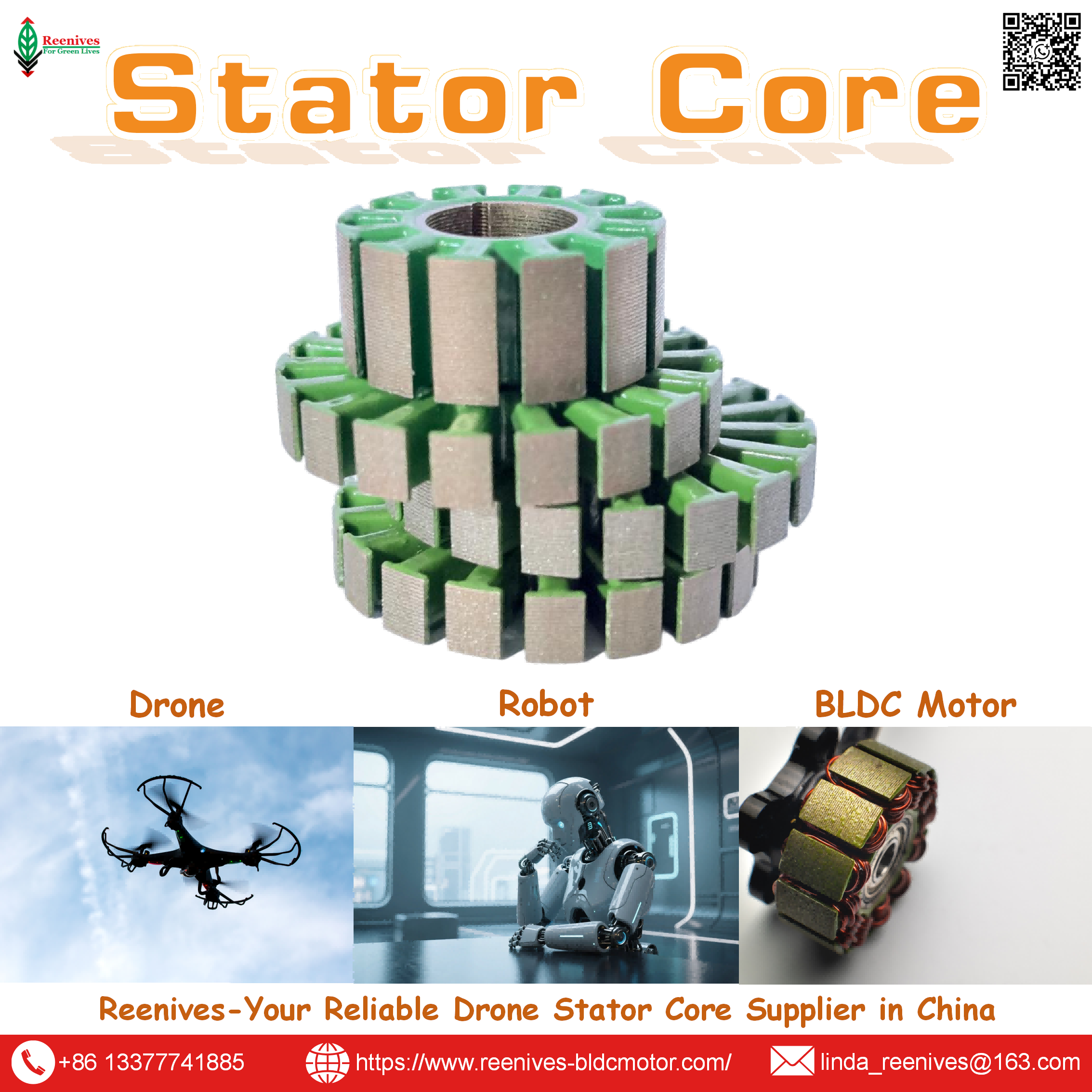
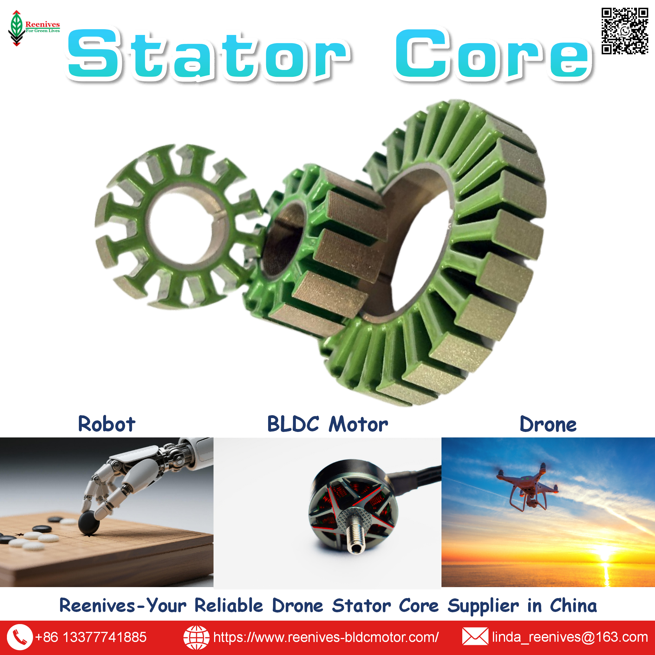
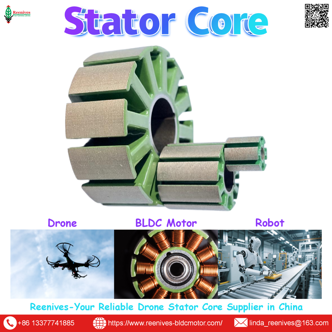
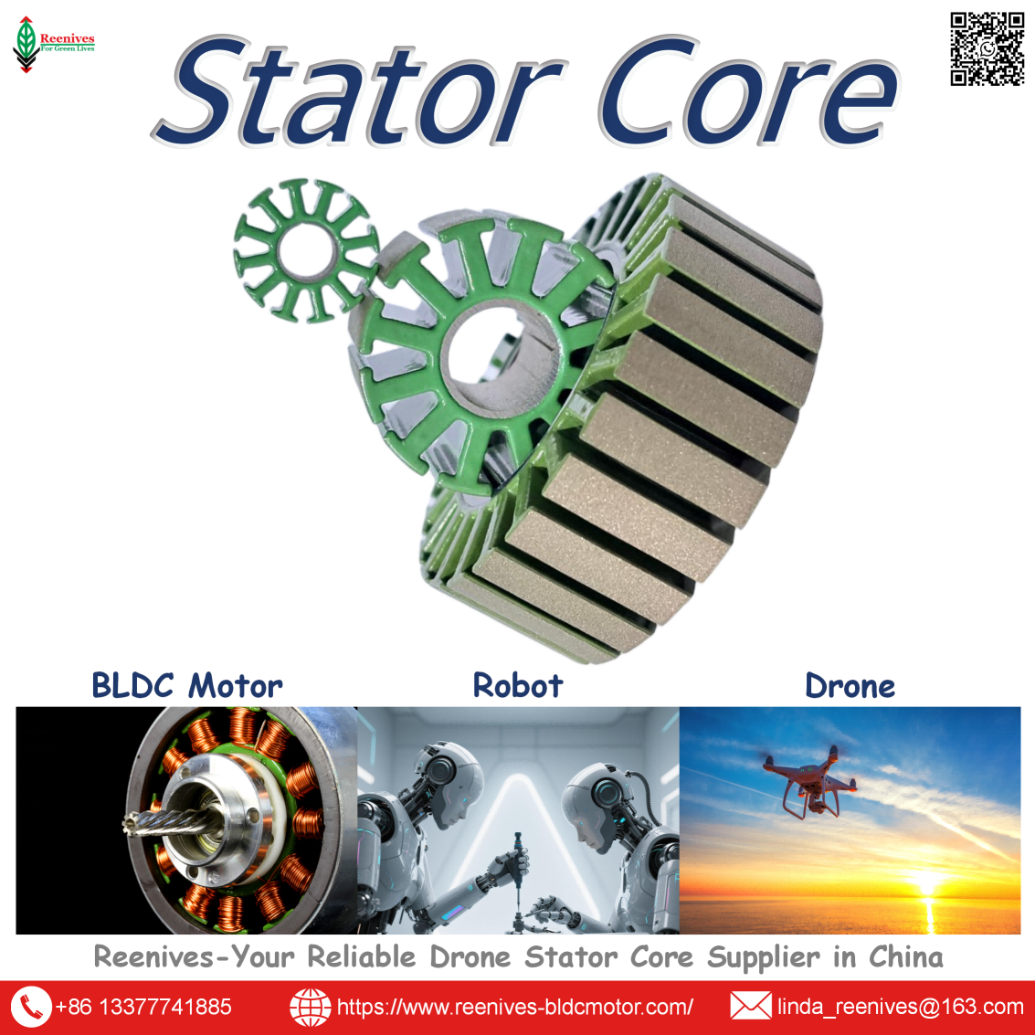
The PD Curve’s 10-minute rated power is a thermal boundary, and the stator core is the component that sets it. Published comparison data at 1.0 T / 400 Hz is specific: 0.35 mm electrical steel runs at roughly 28–35 W/kg; a generic 0.20 mm grade runs at ~10–14 W/kg; and Reenives publishes ≤9.6 W/kg (typical 9.2 W/kg) for its 0.20 mm grade measured by the Epstein frame per IEC 60404-2 and GB/T 3655-2022. The 0.35 → 0.20 mm switch reduces eddy-current loss by approximately 67% at the same flux density, and the published motor-level consequence is roughly 15–25°C lower steady-state winding temperature and 8–12% more continuous torque before thermal derating.
| Lamination Thickness | Published Core Loss @ 1.0 T / 400 Hz | Best Fit | Relative Cost |
|---|---|---|---|
| 0.35 mm | ~28–35 W/kg | Industrial servo ≤3,000 RPM, low-speed torque motors | Low |
| 0.27 mm | ~18–24 W/kg | Mid-speed servo 3,000–8,000 RPM, robot joint actuators | Medium |
| 0.20 mm (generic) | ~10–14 W/kg | High-speed UAV, FPV, frameless motors | High |
| 0.20 mm (Reenives specification) | ≤9.6 W/kg (typical 9.2) | Drone propulsion, agricultural UAV, eVTOL | High |
Sources: HIMAGNET lamination thickness comparison (0.35 mm ~28–35 W/kg; 0.27 mm ~18–24 W/kg; 0.20 mm ~10–14 W/kg); Reenives 0.20 mm specification (≤9.6 W/kg typical 9.2, IEC 60404-2).
The full stator core parameter set for a 2027 specification
| Parameter | Reenives Published Value | Test Standard / Method | Motor-Level Consequence |
|---|---|---|---|
| Core loss (P1.0/400) | ≤9.6 W/kg (typical 9.2 W/kg) | Epstein frame / IEC 60404-2 and GB/T 3655-2022 | Iron heat and continuous power boundary |
| Lamination thickness | 0.20 mm ±0.008 mm (0.15 mm on request) | Micrometer / ASTM A677 | Eddy-current loss scaling with t² |
| B50 flux density | ≥1.69 T | Single strip tester | Torque per unit magnet field |
| Stack height tolerance | ±0.04 mm (≤50 mm); ±0.06 mm (>50 mm) | CMM / Reenives QA | Axial alignment and rotor position |
| Insulation coating | C5 epoxy, >1400 V dielectric strength | ASTM D149, UL 1446 | Interlaminar insulation and winding survival |
| Burr height (max) | ≤0.03 mm | ISO 2768-m / vision system | Prevents coating piercing and interlaminar short |
| Operating temperature | −40°C to 180°C (short peak 200°C) | Thermal cycle test | Insulation survival at continuous duty |
| Stacking factor | ≥95% (95–97% published range) | Weight / dimension method | Effective steel in the stack |
Source: Reenives 0.20 mm laminated core specification (core loss, thickness, B50, stack height tolerance, C5 coating, dielectric strength, burr, operating temperature); published stacking factor range (95–97%).
The 2027 “same 0.20 mm” trap: the label “0.20 mm” does not guarantee the published core loss. A generic 0.20 mm grade runs at ~10–14 W/kg; the Reenives specification runs at ≤9.6 W/kg. Both are 0.20 mm. The difference is grade and process control, and it is worth roughly 5–15°C of winding temperature at the operating point. A 2027 RFQ that names the thickness but not the core-loss value, the test standard, and the measurement location has left the thermal ceiling to the supplier’s default.
Application Profiles: Which Rating Binds Which UAV Mission
| Mission Class | Binding PD Curve Segment | Published Thermal / Power Reference | Specification Priority |
|---|---|---|---|
| Agricultural spraying (10–20 min continuous) | 10-minute rated power | Published Class F temperature-rise limit 105 K; 0.20 mm core to hold the thermal boundary | Continuous power at mission ambient, with a finished-stack core-loss report |
| Heavy-lift logistics (takeoff burst + cruise) | 30-second overload and 10-minute rated | Published PD Curve framework (30 s overload / 10 min rated) | Both the overload margin and the continuous rating, with the test condition stated |
| FPV racing / high-speed | 1-second peak and thermal recovery | 0.20 mm grade at ~1,000+ Hz electrical frequency | Core loss at the high-frequency operating point; burst thermal capacity |
| Long-endurance survey / inspection | 10-minute rated power (or longer) | Flight-validated 3–6 kW/kg benchmark | Efficiency at cruise and continuous thermal margin, not peak power |
| eVTOL / urban air mobility | All three segments, with redundancy | ASTM F2840-2026a and IEC 60034 framework | PD Curve plus fault tolerance and thermal validation against a named standard |
The pattern is that the binding PD segment tracks the mission’s duty cycle. Spray drones bind on the 10-minute rated power because the mission is continuous and thermal. Heavy-lift binds on both the 30-second overload and the continuous rating because takeoff and cruise stress different thermal regimes. FPV binds on the 1-second peak and the high-frequency core loss because the burst is short but the electrical frequency is high. And eVTOL binds on all three because the certification framework demands evidence at every time scale.
A 5-Step 2027 UAV Motor Selection Workflow
- Start from the mission’s continuous thermal load, not the peak thrust. Calculate maximum takeoff weight and the per-motor hover thrust. Apply a thrust-to-weight target of 2.0–2.5:1 for stable control, not the absolute thrust ceiling. Published matching guidance places the efficient operating point at 50–55% throttle and recommends a 20–30% current margin on the ESC. The number you carry into motor selection is the continuous thrust at hover, not the burst thrust at full throttle.
- Match KV to the propeller and voltage platform, then confirm the stator frame size. Published matching rules are direct: low KV + large props, high KV + small props. A 25 kg quadcopter needing 12.5 kgf per powertrain typically points to a 30×10 propeller and a mid-to-low KV motor. Then confirm the stator frame size supports the continuous torque — a 62 mm frame with 24N28P for 5–7.5 kg per rotor, an 83 mm frame with 36N42P for 12–14 kg per rotor. The frame size is the first-order continuous-torque variable; KV is the gearing.
- Specify the stator core with the full parameter set, and require a finished-stack report. Write 0.20 mm non-oriented silicon steel, core loss ≤9.6 W/kg at 1.0 T / 400 Hz per IEC 60404-2 on the finished stack, B50 ≥1.69 T, stacking factor ≥95%, stack height tolerance ±0.04/±0.06 mm, burr ≤0.03 mm, and C5 epoxy at >1400 V per ASTM D149 across −40°C to 180°C. A mill certificate reports a material property; the finished-stack report reports the part you will install. Ask for both, and ask which one the core-loss figure was measured on.
- Demand the PD Curve at three time scales, each with its thermal test condition. Require the continuous power at the mission duration, the 30-second overload, and the 1-second peak, and ask for the test standard behind each — IEC 60034 / GB/T 755 for temperature rise, with the insulation class stated (Class F: 105 K by resistance). A motor that quotes 17.5 kg peak thrust but cannot state its 10-minute rated power has given you a burst number, not a mission number. The PD Curve is the 2027 specification; a single peak number is the 2024 specification.
- Verify 100% end-of-line coverage and review the rejected unit, then confirm the supply-chain timeline. Specify Hi-Pot, surge waveform, three-phase resistance, no-load current, speed, noise, and three-phase balance on every unit, with balancing to G2.5 or better. Ask for a rejected unit from the inspection process — that is the evidence that the process measures what it claims. Then confirm the supplier’s 2027 capacity position: published data shows Sanrui Intelligent’s expansion completing in late 2026 and ramping through 2027, with an S200 motor at 120 kg rated thrust and 235 kg peak thrust. Capacity is loosening, but technical qualification remains the gate.
FAQ: PD Curve, Stator Core Loss, Power Density, Core Parameters, Supply Chain, and Thermal Standards
What is the power-duration (PD) curve standard expected for UAV motors in 2027?
Industry roadmaps for heavy-lift UAV motors state that in 2027 the sector will establish a Power Duration (PD) Curve standard that explicitly defines a motor’s power boundary at different time scales: 1-second peak, 30-second overload, and 10-minute rated power. The stated purpose is to prevent “virtual rating” from misleading the market — a motor that claims a high peak power but cannot sustain it for a mission duration. For procurement, this changes the selection question from “what is the peak thrust?” to “what power can the motor deliver continuously for the mission’s thermal steady state, and what is the time-limited overload margin?”
Source: Published heavy-lift UAV motor technical roadmap (2027 PD Curve standard: 1 s peak, 30 s overload, 10 min rated).
Why does stator core loss matter more than peak torque in a 2027 UAV motor selection?
Because the continuous rating is a thermal limit set by the stator, not a magnetic limit set by the magnets. Published comparison data at 1.0 T / 400 Hz places 0.35 mm electrical steel at roughly 28–35 W/kg and a 0.20 mm drone grade at ~10–14 W/kg, with Reenives publishing ≤9.6 W/kg (typical 9.2 W/kg) for its 0.20 mm grade per IEC 60404-2. The 0.35 → 0.20 mm switch reduces iron loss by approximately 31%, which published analysis translates to roughly 15–25°C lower winding temperature and 8–12% more continuous torque before thermal derating. A motor with a high peak torque rating and a 0.35 mm core will derate earlier than a motor with a lower peak rating and a 0.20 mm core, because the core loss becomes winding heat.
Source: HIMAGNET lamination comparison (0.35 mm ~28–35 W/kg; 0.20 mm ~10–14 W/kg); Reenives 0.20 mm specification (≤9.6 W/kg, IEC 60404-2); published iron-loss thermal analysis (15–25°C, 8–12% continuous torque).
What power density should a 2027 UAV motor benchmark against?
Published benchmarks separate into three tiers. Flight-validated commercial aviation motors (Safran ENGINeUS 100, magniX magniAIR, BETA H500A) sit at roughly 3–6 kW/kg. Laboratory and concept designs converge at 15–18 kW/kg for conventional (non-superconducting) machines, with published examples including a 5.21 kW/kg optimized six-phase PMSM for UAV propulsion, a 17.1 kW/kg MIT-Mitsubishi 1 MW outrunner, and a 19.4 kW/kg Helix design. Superconducting concepts target 28–40 kW/kg but are not procurement options. For a UAV programme, the relevant benchmark is the flight-validated tier plus the specific continuous rating at the mission duty, not the laboratory ceiling.
Source: Published aviation electric propulsion review (flight-validated 3–6 kW/kg; 15–18 kW/kg convergence); IEEE six-phase PMSM (5.21 kW/kg, 96.47%).
What stator core parameters should a 2027 UAV motor specification carry?
The specification should carry the full value-plus-standard-plus-location set for the core. Reenives publishes 0.20 mm non-oriented silicon steel at core loss ≤9.6 W/kg (typical 9.2 W/kg) at 1.0 T / 400 Hz measured by the Epstein frame per IEC 60404-2 and GB/T 3655-2022, with B50 flux density ≥1.69 T, stacking factor ≥95% (95–97% published range), stack height tolerance ±0.04 mm for stacks ≤50 mm and ±0.06 mm for stacks >50 mm, concentricity ≤0.02 mm, burr height ≤0.03 mm by vision system, C5 epoxy coating at >1400 V dielectric strength per ASTM D149 and UL 1446, and operating range −40°C to 180°C with a 200°C short-term peak. Each line is expressed as a number plus a test standard plus a measurement location, so it can be verified on the finished part.
Source: Reenives 0.20 mm laminated core specification (core loss, thickness, B50, stack height tolerance, C5 coating, dielectric strength, burr, operating temperature); published stacking factor range (95–97%).
How does the 2027 supply chain change UAV motor sourcing?
Published supply-chain data shows a capacity release scheduled for 2027. Sanrui Intelligent (三瑞智能), the world’s second-largest civil UAV electric propulsion supplier by 2024 market share, began an expansion project in July 2025 with completion expected by the end of 2026 and capacity release through 2027. The company reports power density of 7.84 W/g and an S200 motor with 120 kg rated thrust and 235 kg peak thrust. Its products ship to more than 100 countries. For a buyer, the 2027 implication is that qualified supplier capacity increases and lead times may shorten, but the technical qualification criteria — stator core loss, thermal rating, and PD Curve compliance — remain the gating factors, not the availability of motors.
Source: Published Sanrui Intelligent expansion timeline (July 2025 start, end-2026 completion, 2027 capacity release; 7.84 W/g; S200 120 kg rated / 235 kg peak; 100+ countries).
What thermal test standard applies to UAV motors in 2026–2027?
The relevant standards are layered. IEC 60034 (rotating electrical machines) and GB/T 755 define temperature-rise limits and measurement methods; for a Class F insulation winding, the temperature-rise limit is typically 105 K by the resistance method. IEC 60317 or NEMA MW 35-C covers high-temperature enameled wire for the winding itself, with thermal class ratings typically 180°C–240°C for agricultural drone motors. ASTM F2840-2026a, issued by the ASTM F38 unmanned systems committee and effective 1 May 2026, provides a design-and-manufacture standard for electric motors in light sport aircraft, covering thermal management and test verification. A UAV motor specification should state which of these applies to its thermal validation, because “rated power” without a stated test standard and duty cycle is not an auditable number.
Source: IEC 60034 / GB/T 755 temperature-rise limits (Class F 105 K); IEC 60317 / NEMA MW 35-C thermal class 180°C–240°C; ASTM F2840-2026a effective 1 May 2026, ASTM F38 committee.
How should a procurement engineer build the 2027 UAV motor selection workflow?
Start from the mission’s continuous thermal load, not the peak thrust. Calculate maximum takeoff weight and the per-motor hover thrust, then apply a thrust-to-weight target of 2.0–2.5:1 rather than the absolute ceiling. Select the propeller diameter from the thrust requirement, then match KV to the propeller and voltage platform (low KV for large props, high KV for small props). Specify the stator core with the full core-loss, stacking-factor, and tolerance set, and require a finished-stack core-loss report at the operating electrical frequency. Then demand the PD Curve: continuous power at the mission duration, 30-second overload margin, and 1-second peak, each with its thermal test condition. Finally, verify 100% end-of-line coverage and a rejected unit from the supplier’s inspection process.
Source: Published multirotor propulsion matching guide (thrust-to-weight 2.2–2.5, 50–55% throttle, low KV + large props, 20–30% ESC margin); published PD Curve framework; Reenives stator core specification.
Summary: Specify the Continuous Boundary, Then Verify It
The 2027 UAV motor selection question is not “what is the peak thrust?” It is “what power can the motor deliver at the mission’s thermal steady state, what overload margin exists above it, and what stator core loss sets the boundary?” The PD Curve makes those three numbers explicit; the stator core makes them real. Published data is concrete: 0.35 mm steel at roughly 28–35 W/kg, a generic 0.20 mm grade at ~10–14 W/kg, and the Reenives 0.20 mm specification at ≤9.6 W/kg per IEC 60404-2 — a difference that translates to 15–25°C of winding headroom and 8–12% more continuous torque. The power-density benchmark splits into flight-validated 3–6 kW/kg and laboratory 15–18 kW/kg; a procurement specification should anchor to the former and the specific continuous rating, not the latter.
The procurement takeaway is that a 2027 specification has to name the time scale. A motor rated “17.5 kg peak thrust” and a motor rated “X kg at 10 minutes continuous” are not the same claim, and a supplier who offers only the first has not described the second. Ask for the PD Curve, ask for the finished-stack core-loss report at the operating electrical frequency, and ask for the thermal test standard behind each rating. Those three requests separate a motor that flies a demo from a motor that holds a mission.
Building a 2027 UAV motor specification?
Reenives publishes the stator core parameters that set your continuous thermal boundary: 0.20 mm non-oriented silicon steel, core loss ≤9.6 W/kg (typical 9.2) at 1.0 T / 400 Hz per IEC 60404-2 and GB/T 3655-2022, B50 ≥1.69 T, stacking factor ≥95%, stack height tolerance ±0.04/±0.06 mm, concentricity ≤0.02 mm, burr ≤0.03 mm, and C5 epoxy coating at >1400 V per ASTM D149 across −40°C to 180°C. Finished-stack reports, matched stator-rotor pairs, private mould development, and free samples are available for qualified engineering evaluations.
WhatsApp: +86-13377741885
Email: linda_reenives@163.com
Official website: www.reenives-bldcmotor.com
Dongguan Runlu Motor Technology Co., Ltd.
Reenives — Drone Motor One-Stop Solution Supplier
Reenives is a professional drone stator core manufacturer, founded in 2022. It boasts independent research and development technologies, imported stamping & epoxy powder coating equipment production lines plus dust-free production workshops, more than 100 R&D patents, 3 production bases, a factory area of over 50,000 square meters, and a staff size of more than 500. From production to sales, we support bulk purchasing, private mould development, and sample making, and can provide tailor-made perfect solutions for your production and usage scenarios. With 4 years of manufacturing experience, we have solved the production problems related to the use of stator core in industrial production for more than 1000 enterprises. We can ship globally (with complete export qualifications). Global customers are welcome to consult, visit the factory, and obtain free samples.
0.20 mm silicon steelCore loss ≤9.6 W/kg @ 1.0 T / 400 HzB50 ≥1.69 TStacking factor ≥95%Stack height ±0.04/±0.06 mmBurr ≤0.03 mmC5 epoxy >1400 V12N14P · 24N28P · 36N42PGlobal export qualifications
What is Agriculture Drone Motor Price?
How to Manufacture Motor De Drone?
Related Article