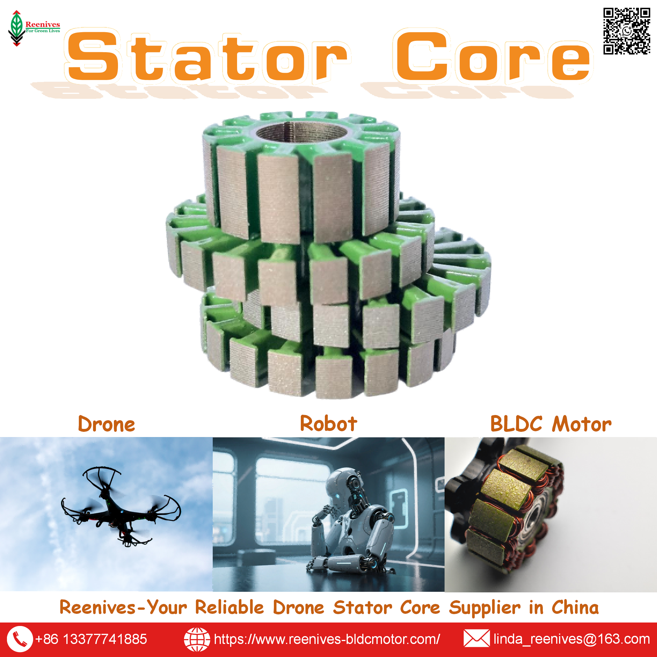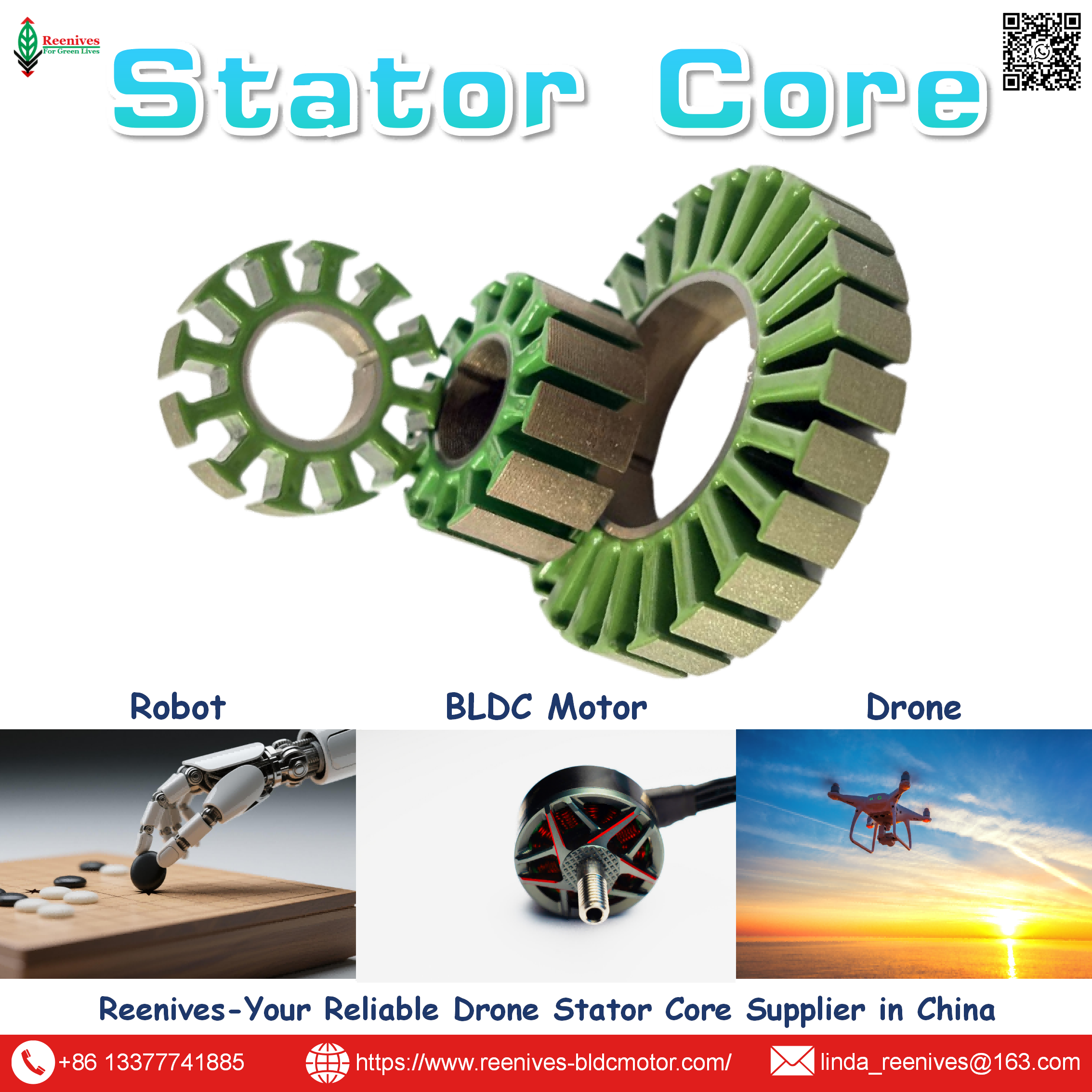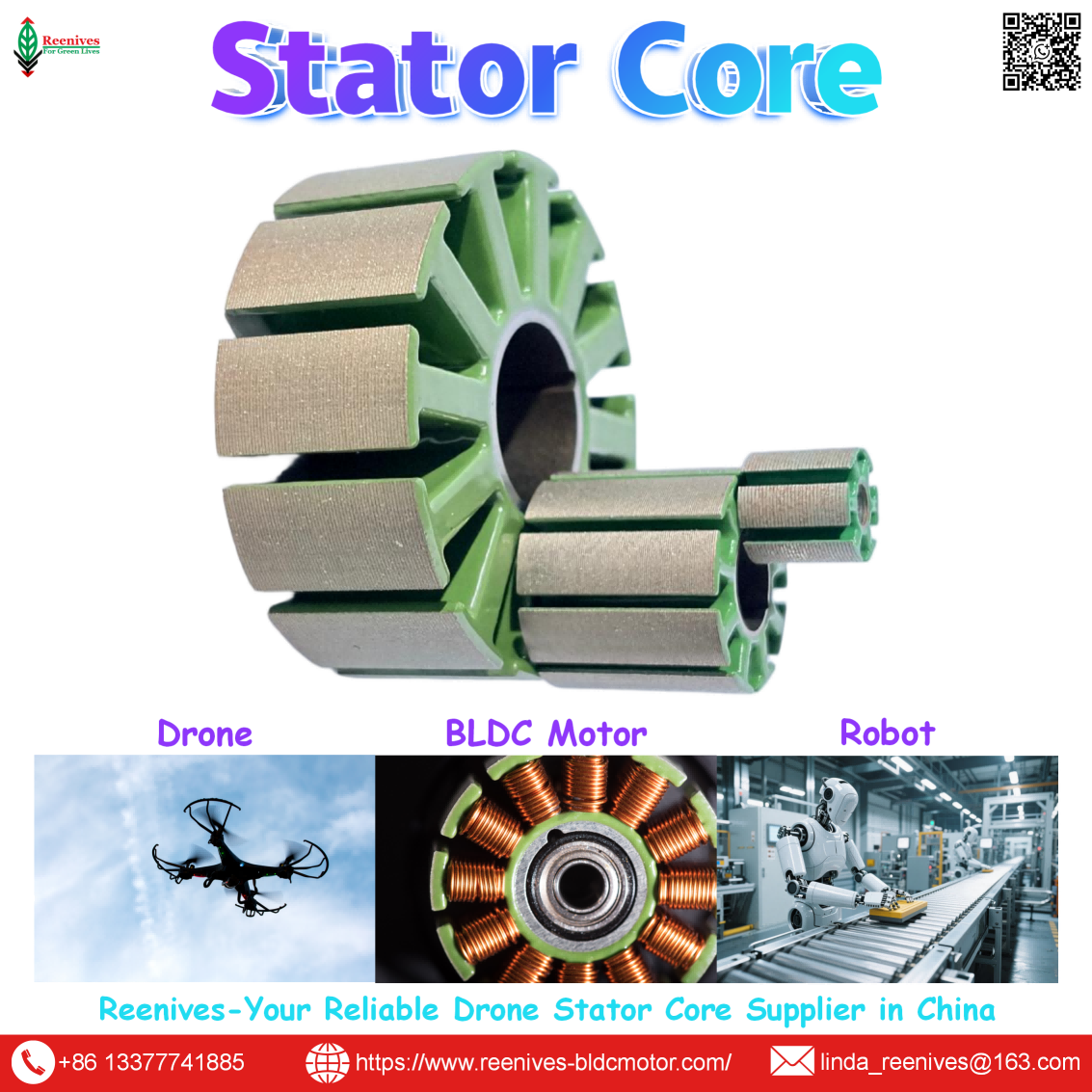
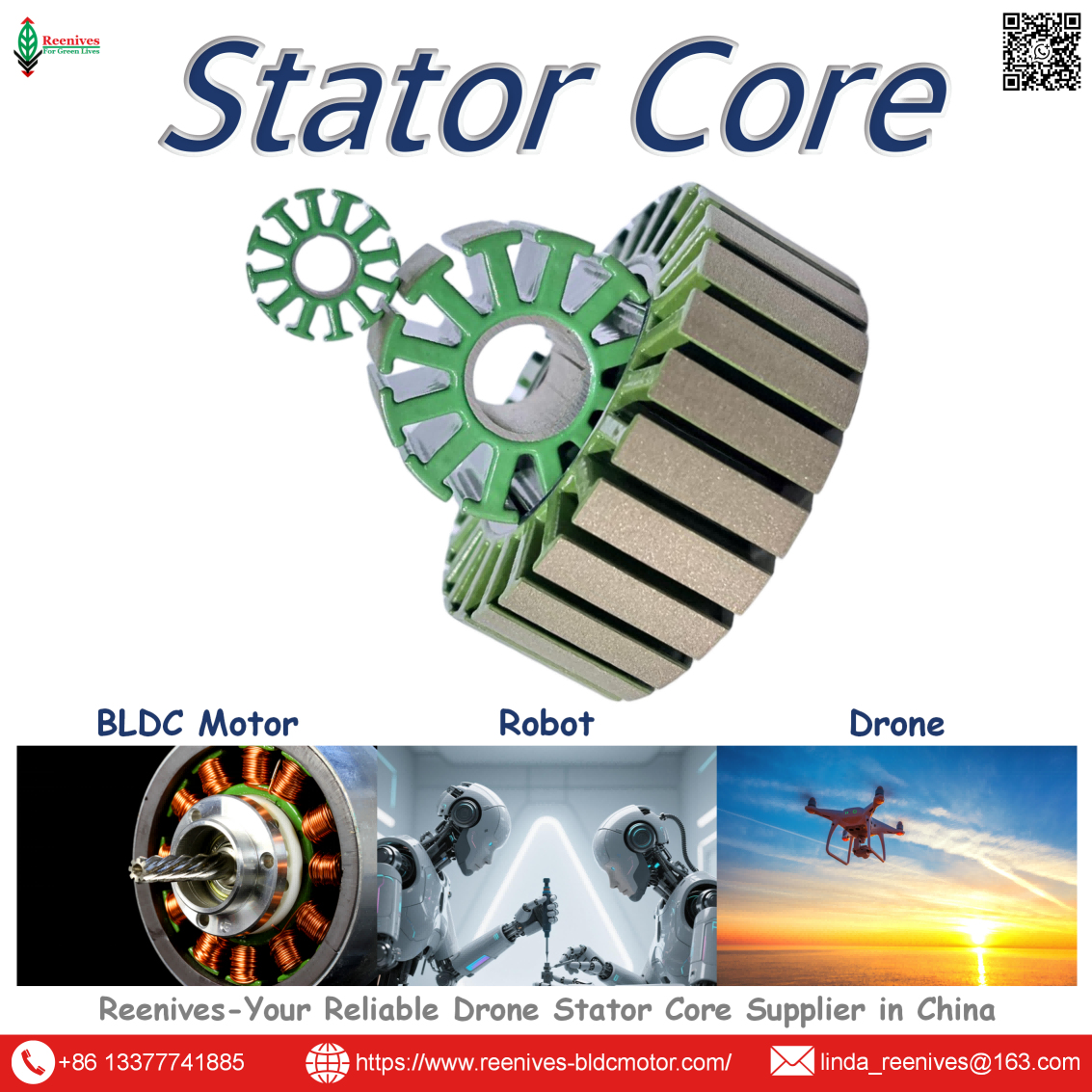
Size of Agriculture Drone Motor Stator
Size of Agriculture Drone Motor Stator: How OD × Stack Height Maps to Payload, Torque, and Spray Duty
Two agriculture drone motors can both be rated “100 KV, 12S” and still differ by a factor of two in the stator steel they contain. One is a 62 mm × 15 mm frame with a 24N28P winding, rated around 2,175 W continuous. The other is an 83 mm × 18 mm frame with a 36N42P winding, rated around 2,500 W continuous and capable of 17.5 kg of thrust on a 28–32 inch propeller. The KV rating is identical. The stator size is not. For a spray drone that must carry 16 litres of pesticide through a 20-minute mission in high ambient heat, the stator size is the variable that decides whether the motor holds its rated thrust or derates halfway through the field. Published motor-model guidance is direct: a larger stator diameter usually increases torque, and a greater stack height increases core length. Those are two separate dimensions doing two separate jobs.
This guide breaks down the size of an agriculture drone motor stator at the level a procurement engineer or propulsion lead needs: how the size is expressed, the published frame families and their payload classes, the slot-pole and lamination parameters that go with each frame, the thermal and torque consequences of the diameter-versus-stack-height trade, and a five-step sizing workflow that starts from the spray tank and ends with a stator specification. Every figure is expressed as a value plus a published source, so it can be checked against a supplier datasheet rather than taken on faith.
In this guide — jump to the section your project needs:
- What Does “Size of Agriculture Drone Motor Stator” Mean? The OD × Stack Height Definition
- Stator Frame Classification: 31 mm, 50–62 mm, 69–83 mm, and the Slot-Pole Families Inside Each
- Published Parameters by Frame: Stack Height, Slot-Pole, Lamination Gauge, Continuous Power, and Thrust
- Application Profiles: Mapping Tank Size to Stator Size
- A 5-Step Sizing Workflow: From Spray Tank to Stator Specification
- FAQ: Size Expression, Tank-to-Frame Mapping, Diameter vs Stack Height, Lamination, Thermal Rating, and RFQ Parameters
- Summary: Size the Stator for the Spray Window, Not the Peak Thrust
What Does “Size of Agriculture Drone Motor Stator” Mean? The OD × Stack Height Definition
The size of an agriculture drone motor stator is expressed as outer diameter × stack height, and the same two numbers appear in the motor model name. Published motor-model guidance states the convention directly: a 3115 motor has a 31 mm stator outer diameter and a 15 mm stack height; a 2207 has a 22 mm diameter and a 7 mm stack; a 4214 has a 42 mm diameter and a 14 mm stack. The first two digits of the model number are the stator OD in millimetres; the last two digits are the stack height in millimetres. That naming convention is the fastest way to compare two agriculture motors on the same page.
| Dimension | What It Sets | Published Guidance | Agriculture Consequence |
|---|---|---|---|
| Stator outer diameter | Magnetic pole area and lever arm | “Larger stator diameter usually increases torque” | Dominant first-order variable for low-RPM torque at large propeller diameters |
| Stack height | Core length and magnetic steel volume | “Greater stack height increases core length” | Fine-tunes torque constant and thermal mass without increasing motor footprint diameter |
| Aspect ratio (OD / stack) | Torque-density vs axial-length trade | Published teardown motors span aspect ratios from 1.4 to 9.0 | A tall, narrow stator trades axial length for diameter; agriculture motors trend toward wide, short stacks |
Sources: Published motor-model guidance (OD × stack height convention; diameter increases torque, stack height increases core length); published teardown motor aspect ratio data (1.4–9.0).
The dimension that is routinely under-specified in a purchase order is the one that matters most for a spray drone: the continuous thermal rating, which scales with the magnetic steel mass and surface area that the OD and stack height together define. A larger stator is not simply a stronger motor — it is a larger thermal reservoir. A 62 mm × 15 mm stator motor is rated around 2,175 W maximum continuous power in published data; an 83 mm × 18 mm stator motor is rated around 2,500 W. For a 10–20 minute spray mission at near-continuous load, that continuous rating is the number that constrains the spray window, not the peak thrust on the datasheet.
Procurement translation: a motor spec that says “6215, 170 KV” has named the stator diameter (62 mm) and the stack height (15 mm) — but not the slot-pole configuration, the lamination gauge, the continuous thermal rating, or the stator core loss at the operating frequency. Those four parameters are what determine whether the 62×15 frame actually delivers its rated thrust in a 45°C field. The size is the starting point; the specification is the size plus the parameters inside it.
Stator Frame Classification: 31 mm, 50–62 mm, 69–83 mm, and the Slot-Pole Families Inside Each
Frame families by stator outer diameter
| Frame Class | Published Stator Size | Slot-Pole | Typical KV | Published Power / Thrust | Agriculture Role |
|---|---|---|---|---|---|
| 31 mm class | 31 × 15 mm | — | 850–1,100 KV | 116–125 g motor weight; 4S–8S | Light-lift / auxiliary; not a primary spray motor |
| 50 mm class | 50 × 8 mm | — | 335–400 KV | 180 g; 0.2 mm Kawasaki silicon steel | High-speed spray drone auxiliary |
| 60 mm class | 60 × 10 mm | — | 130 KV | 5.1 kg max thrust per rotor; 770 W max | 10 kg payload spray platform |
| 62 mm class | 62 × 15 mm | 24N28P | 170–175 KV | ~2,175 W max continuous; 345–375 g | 10L–16L spray quad/hex; 5–7.5 kg rated thrust per rotor |
| 69 mm class | 69 × 37 mm (motor) | 24N28P | 170 KV | 1,800 W max (180 s); 38 A max continuous | 16L platform propulsion |
| 83 mm class | 83 × 18 mm | 36N42P | 100–120 KV | ~2,500 W max continuous; 635 g; 17.5 kg thrust | 20L+ spray / heavy lift; 28–32 inch propeller |
Sources: Atlas 3115 (31×15 mm, 850–1,100 KV, 116–125 g); TYI 5008 (50×8 mm, 335–400 KV, 180 g, 0.2 mm Kawasaki silicon steel); CHH spray drone (60×10 mm, 130 KV, 5.1 kg thrust, 770 W); Mecwin/P60 6215 (62×15 mm, 24N28P, 170–175 KV, ~2,175 W, 345–375 g); Mecwin M60 (69 mm motor, 24N28P, 1,800 W, 38 A); MAD 8318 (83×18 mm, 36N42P, 100–120 KV, 635 g, 17.5 kg thrust).
Slot-pole families inside the frame
The slot-pole configuration is the second half of the stator size specification, and it is fixed at the core design stage. Published data separates the families by frame class: the 62 mm class typically uses 24N28P; the 83 mm class moves to 36N42P; and published agriculture/industrial lamination guidance also cites 9N12P as a common configuration for wider-tooth, higher-torque applications in the 400–800 Hz band. A published UAV stator family progression shows the same pattern: the stator configuration grows from 12N14P in a 41.8 mm envelope to 24N28P at 69 mm and 36N42P at 91.6 mm, with published thrust rising from 1,800 g to 8,414 gf to 16,344 g along the same progression.
Published Parameters by Frame: Stack Height, Slot-Pole, Lamination Gauge, Continuous Power, and Thrust
| Frame | Stator Size | Slot-Pole | Lamination / Core Notes | Continuous Power | Published Thrust |
|---|---|---|---|---|---|
| 3115 | 31 × 15 mm | — | — | — | — |
| 5008 | 50 × 8 mm | — | 0.2 mm Kawasaki silicon steel | — | — |
| 60×10 spray | 60 × 10 mm | — | — | 770 W max | 5.1 kg max per rotor |
| 6215 | 62 × 15 mm | 24N28P | 0.20–0.25 mm recommended for 400–800 Hz agriculture band | ~2,175 W max | — |
| 69 mm class | 69 mm motor | 24N28P | — | 1,800 W max (180 s) | — |
| 8318 | 83 × 18 mm | 36N42P | — | ~2,500 W max | 17.5 kg max · 28–32 inch prop |
Sources: Atlas 3115; TYI 5008 (0.2 mm Kawasaki silicon steel); CHH spray drone (60×10 mm, 770 W, 5.1 kg); Mecwin/P60 6215 (62×15 mm, 24N28P, ~2,175 W); Mecwin M60 (1,800 W, 38 A); MAD 8318 (83×18 mm, 36N42P, 17.5 kg, 28–32 inch prop); published agriculture lamination guidance (0.20–0.25 mm for 400–800 Hz).
Lamination gauge and stacking method for agriculture stators
Published drone lamination guidance places agriculture and industrial motor configurations at 9N12P, with typical electrical frequencies of 400–800 Hz and recommended lamination gauges of 0.20–0.25 mm. The core-loss reduction versus 0.35 mm steel in this band is approximately 50–65%. The stacking method matters as well: published production data places adhesive bonding at roughly 5–8% lower core loss than interlocked stacks and 8–15% lower than laser-welded stacks, because interlock tabs and weld zones create localized short-circuit paths that are measurable on a 15 mm stack. Interlocking remains the volume choice for speed and cost; bonding is the better choice where thermal margin is the primary metric — which is exactly the case for a spray drone operating near its continuous rating.
Thermal rating: the parameter that constrains the spray window
Published agriculture motor data shows the continuous power rating rising with stator size: the 62 mm × 15 mm 24N28P frame is rated around 2,175 W maximum continuous, while the 83 mm × 18 mm 36N42P frame is rated around 2,500 W. That difference is not only electromagnetic — it is the thermal mass and surface area that allow the larger stator to sustain a higher current without derating. A spray drone flies 10–20 minutes at near-continuous load in high ambient heat. The number that determines how much area the drone can cover per sortie is the continuous rating, not the peak thrust.
The KV-only sizing trap: two agriculture motors can both be rated 100 KV and differ by a factor of two in stator steel. A 62 mm × 15 mm frame and an 83 mm × 18 mm frame can be wound to the same KV, but the larger frame has more magnetic pole area, more thermal mass, and a higher continuous power rating. Sizing a spray drone by KV alone selects a motor that may hover correctly at full tank and still derate by mid-mission. The stator size — OD × stack height — is the first specification, and the KV follows from the propeller and voltage platform.
Application Profiles: Mapping Tank Size to Stator Size
| Spray Tank Class | Published Rated Thrust per Rotor | Typical Stator Frame | Slot-Pole | KV / Voltage |
|---|---|---|---|---|
| 4L–6L | 4–6 kg | Light-lift frame; 31–50 mm class | — | 130–150 KV / 12S–14S |
| 10L–12L | 5–7.5 kg | 60–62 mm class | 24N28P | 100–130 KV / 12S |
| 12L–16L | 7–12 kg | 62–69 mm class | 24N28P | 100–170 KV / 12S–14S |
| 20L+ | 12–14 kg | 83 mm class | 36N42P | 85–120 KV / 12S–14S |
| 25L–30L+ | 17+ kg | 83 mm class or larger | 36N42P | ~45 KV / 18S |
Sources: Hobbywing X-series rated thrust per rotor by tank class (X6 Plus 4–6 kg; X8 5–7.5 kg; X9 G2L 7–12 kg; X9 Plus G2L 12–14 kg; X11 G2 17 kg; X13 18S ~45 KV); published 6215/8318 frame data; published spray drone 60×10 mm frame (5.1 kg thrust, 10 kg payload).
The pattern is that the stator frame class steps up with the tank class, and the KV steps down. A 10L quadcopter on a 60–62 mm frame runs 100–130 KV on 12S; a 20L+ platform on an 83 mm frame runs 85–120 KV on 12S–14S; a 25–30L platform pushes to 18S and approximately 45 KV. The reason is physical: larger propellers move a bigger column of air per rotation and generate the same thrust at lower RPM, so the motor must trade RPM for torque. That trade is executed through stator size — wider diameter for torque, taller stack for core length — not through KV selection alone.
A 5-Step Sizing Workflow: From Spray Tank to Stator Specification
- Start from the tank class and the all-up weight, not from a motor model. State the tank volume, the number of rotors, and the all-up weight with a full tank. Published propulsion data maps tank class to rated thrust per rotor: 10L platforms typically sit at 5–7.5 kg per rotor, 16L at 7–12 kg, and 20L+ at 12–14 kg. Multiply by the rotor count and apply the thrust-to-weight target (published guidance places stable hover targets at 2:1 to 2.5:1, not the absolute thrust ceiling) to get the required thrust per motor.
- Select the stator frame class from the thrust requirement, then confirm the slot-pole. A 62 mm × 15 mm frame with 24N28P serves the 5–7.5 kg per-rotor class; an 83 mm × 18 mm frame with 36N42P serves the 12–14 kg class and up. Confirm the slot-pole configuration is available in the frame you are quoting — 24N28P and 36N42P are different lamination dies, not interchangeable windings. Published agriculture/industrial configurations also include 9N12P for wider-tooth, higher-torque applications.
- Specify the lamination gauge against the electrical frequency, not against a generic grade. Calculate fe = RPM × (poles/2) / 60. For agriculture motors in the 400–800 Hz band, published guidance recommends 0.20–0.25 mm non-oriented silicon steel, with 50–65% core-loss reduction versus 0.35 mm. Reenives publishes 0.20 mm grade at core loss ≤9.5 W/kg at 1.0 T / 400 Hz per IEC 60404-2, stacking factor ≥97%, and burr <0.03 mm. A supplier who can only provide 50/60 Hz loss data has not specified the stator for spray duty.
- Confirm the continuous thermal rating and the stack-height tolerance for the frame. Ask for the maximum continuous power at the intended ambient (not the 180-second peak) and the stack-height tolerance — published practice places it at ±0.06 mm for stacks up to 80 mm. For a 10–20 minute spray mission, the continuous rating is the number that sets the spray window. A 62 mm × 15 mm frame at ~2,175 W and an 83 mm × 18 mm frame at ~2,500 W are different thermal classes; confirm the rating matches the mission duty.
- Ask for a finished-stack core-loss report and a rejected unit from the inspection process. The stack-height and lamination data on a datasheet describes a nominal part; the finished-stack report describes the part you will install. Ask for the core loss at the operating frequency with the test conditions stated (sinusoidal polarization, 23°C ±5°C, no external stress), the stacking factor, and a unit that failed the burr or stack-height check and was rejected. That rejected unit is the evidence that the inspection process is measuring what it claims.
FAQ: Size Expression, Tank-to-Frame Mapping, Diameter vs Stack Height, Lamination, Thermal Rating, and RFQ Parameters
How is the size of an agriculture drone motor stator expressed?
Stator size is expressed as outer diameter × stack height, and the same numbers appear in the motor model name. A 3115 motor has a 31 mm stator outer diameter and a 15 mm stack height. A 6215 has a 62 mm stator diameter and a 15 mm stack. An 8318 has an 83 mm stator diameter and an 18 mm stack. The first two digits of the model number are the stator OD in millimetres; the last two are the stack height in millimetres. For agriculture drones, published frame sizes span 31×15 mm on light-lift platforms up to 83×18 mm on heavy spray platforms, with 50×8 mm and 60×10 mm frames appearing on intermediate spray systems.
Source: Published motor-model naming convention (OD × stack height); Atlas 3115 (31×15 mm); Mecwin/P60 6215 (62×15 mm); MAD 8318 (83×18 mm); TYI 5008 (50×8 mm); CHH spray drone (60×10 mm).
What stator diameter and stack height should a 10L, 16L, or 20L agriculture drone use?
Published propulsion data maps tank class to rated thrust per rotor, and the stator size follows from that thrust requirement. A 10L quadcopter typically uses 5–7.5 kg rated thrust per rotor, served by motors in the 62 mm stator class (such as the 6215 frame, 24N28P, roughly 170–175 KV). A 16L platform typically uses 7–12 kg rated thrust per rotor and moves to the 69–83 mm stator class. A 20L+ platform uses 12–14 kg rated thrust per rotor, served by the 83 mm class (8318 frame, 36N42P, 100–120 KV). Published frame data places the 8318 at a maximum thrust of 17.5 kg with a 28–32 inch propeller, and the 6215 at approximately 2,175 W maximum continuous power. The mapping is not a rule — it is a starting point that must be verified against the actual all-up weight and thrust-to-weight target.
Source: Hobbywing X-series rated thrust per rotor by tank class (10L: 5–7.5 kg; 16L: 7–12 kg; 20L+: 12–14 kg); Mecwin/P60 6215 (~2,175 W); MAD 8318 (17.5 kg, 28–32 inch prop); published KV guidance for 10L–30L agri motors.
Does stator diameter or stack height matter more for agriculture drone torque?
Both matter, but they do different things. Published motor-model guidance states that a larger stator diameter usually increases torque, while a greater stack height increases core length. In practical terms, diameter sets the lever arm and the magnetic pole area; stack height sets how much magnetic steel the flux can act through. For agriculture drones that need low-RPM, high-torque output to swing 28–32 inch propellers, diameter is the dominant first-order variable, because torque scales with the magnetic area that diameter defines. Stack height is then used to fine-tune the torque constant and the thermal mass without increasing the motor’s footprint diameter. A 62 mm stator with a 15 mm stack and an 83 mm stator with an 18 mm stack are therefore not interchangeable: the larger diameter is the reason the 8318 can deliver 17.5 kg of thrust while the 6215 delivers materially less at the same voltage class.
Source: Published motor-model guidance (diameter increases torque, stack height increases core length); published frame data (6215 vs 8318 thrust and power).
What lamination gauge and stacking method should an agriculture drone stator use?
Published drone lamination guidance places agriculture and industrial motor configurations at 9N12P, with typical electrical frequencies of 400–800 Hz and recommended lamination gauges of 0.20–0.25 mm. The core-loss reduction versus 0.35 mm steel is approximately 50–65% in this frequency band. For the stacking method, published production data is direct: adhesive bonding delivers the best electromagnetic performance, roughly 5–8% lower core loss than interlocked stacks and 8–15% lower than laser-welded stacks, because interlock tabs and weld zones create localized short-circuit paths. Interlocking wins on speed and cost for high-volume production; bonding is the better choice where efficiency and thermal margin are the primary metrics. Reenives publishes 0.20 mm non-oriented silicon steel with core loss ≤9.5 W/kg at 1.0 T / 400 Hz per IEC 60404-2, stacking factor ≥97%, and burr <0.03 mm for its drone stator cores.
Source: Published agriculture/industrial lamination guidance (9N12P, 400–800 Hz, 0.20–0.25 mm, 50–65% reduction vs 0.35 mm); published stacking method comparison (bonding 5–8% lower loss than interlock, 8–15% lower than weld); Reenives 0.20 mm specification.
How does stator size affect the continuous thermal rating of an agriculture drone motor?
Stator size sets the thermal reservoir. A larger stator has more magnetic steel mass and more surface area, so it can absorb and dissipate more heat before the winding reaches its insulation limit. Published agriculture drone motor data illustrates the range: a 62 mm × 15 mm stator motor (6215 frame, 24N28P) is rated for approximately 2,175 W maximum continuous power, while an 83 mm × 18 mm stator motor (8318 frame, 36N42P) is rated for approximately 2,500 W maximum continuous power. The difference is not only electromagnetic — it is the thermal mass that allows the larger motor to sustain a higher continuous current without derating. For spray drones that operate for 10–20 minutes at near-continuous load, the continuous thermal rating is the number that constrains the spray window, not the peak thrust.
Source: Mecwin/P60 6215 (~2,175 W continuous); MAD 8318 (~2,500 W continuous); published agriculture motor thermal analysis.
What stator core parameters should be specified when sourcing an agriculture drone motor stator?
The specification must name the stator outer diameter and stack height (for example 62 mm × 15 mm), the slot-pole configuration (24N28P for the 62 mm class, 36N42P for the 83 mm class, or 9N12P for agriculture/industrial configurations), the lamination gauge and grade (0.20–0.25 mm non-oriented silicon steel for the 400–800 Hz band), core loss at the operating electrical frequency with the test standard, stacking factor, burr height, concentricity or air-gap datum tolerance, and the coating dielectric strength and temperature class. Reenives publishes 0.20 mm silicon steel at core loss ≤9.5 W/kg at 1.0 T / 400 Hz per IEC 60404-2, B50 1.65–1.72 T, stacking factor ≥97%, concentricity ≤0.02 mm, burr <0.03 mm, and C5 epoxy coating at >1400 V per ASTM D149 — the same value-plus-standard-plus-location discipline applies to the larger agriculture frames, with the stack-height tolerance (published ±0.06 mm for stacks up to 80 mm) named explicitly.
Source: Published frame data (6215 24N28P; 8318 36N42P; 9N12P agriculture/industrial); published agriculture lamination guidance (0.20–0.25 mm, 400–800 Hz); Reenives 0.20 mm stator core specification; published stack-height tolerance (±0.06 mm for stacks up to 80 mm).
Can a smaller stator with a taller stack replace a larger stator with a shorter stack?
Only within limits, and never exactly. Published motor-model guidance separates the two dimensions: diameter increases torque by increasing the magnetic pole area and the lever arm, while stack height increases core length. A taller stack on a smaller diameter can recover some torque, but it cannot recover the diameter-dependent magnetic area, and it increases the axial length of the motor — which matters on an agriculture drone where the motor sits above the spray tank and the propeller clearance is fixed. The practical rule is to select the smallest diameter that meets the torque requirement at the target KV and propeller size, then use stack height to fine-tune the torque constant and thermal margin. A 62 mm × 20 mm stack is not a drop-in replacement for an 83 mm × 18 mm stator in a 20L spray platform.
Source: Published motor-model guidance (diameter vs stack height functions); published agriculture drone motor dimensional constraints.
Summary: Size the Stator for the Spray Window, Not the Peak Thrust
The size of an agriculture drone motor stator is written as outer diameter × stack height, and those two numbers map directly to the payload class the motor can serve. The published frame families run from 31×15 mm on light-lift platforms through 62×15 mm (24N28P) on 10–16L spray drones at 5–7.5 kg rated thrust per rotor, to 83×18 mm (36N42P) on 20L+ platforms at up to 17.5 kg thrust with a 28–32 inch propeller. Diameter is the dominant first-order torque variable; stack height fine-tunes the torque constant and the thermal mass.
The parameters inside the frame matter as much as the frame itself. Published agriculture lamination guidance recommends 0.20–0.25 mm non-oriented silicon steel for the 400–800 Hz band, with a 50–65% core-loss reduction versus 0.35 mm steel. Stacking method changes that further: adhesive bonding delivers roughly 5–8% lower core loss than interlocking and 8–15% lower than laser welding. And the continuous thermal rating — ~2,175 W for the 62×15 frame versus ~2,500 W for the 83×18 frame — is the number that actually constrains how much field the drone can spray per sortie.
The procurement takeaway is that a stator size is a starting specification, not a complete one. A supplier who names the OD × stack height and the slot-pole configuration is describing a frame. A supplier who also names the lamination gauge with its finished-stack core loss at the operating frequency, the stacking method, the stack-height tolerance, and the continuous thermal rating is describing a stator that will hold its rating through a full spray mission. For an agriculture drone programme, that distinction is the difference between a motor that works in the demo and one that works in the field.
Sourcing stator cores for an agriculture drone motor programme?
Reenives publishes the stator core parameters that anchor the frame specification: 0.20 mm non-oriented silicon steel, core loss ≤9.5 W/kg at 1.0 T / 400 Hz per IEC 60404-2, B50 1.65–1.72 T, stacking factor ≥97%, concentricity ≤0.02 mm, burr height <0.03 mm, and C5 epoxy coating at >1400 V per ASTM D149, with stack-height tolerance ±0.06 mm for stacks up to 80 mm. Larger agriculture frames are available with 24N28P and 36N42P slot-pole configurations, finished-stack core-loss reports, matched stator-rotor pairs, private mould development, and free samples for qualified engineering evaluations.
WhatsApp: +86-13377741885
Email: linda_reenives@163.com
Official website: www.reenives-bldcmotor.com
Dongguan Runlu Motor Technology Co., Ltd.
Reenives — Drone Motor One-Stop Solution Supplier
Reenives is a professional drone stator core manufacturer, founded in 2022. It boasts independent research and development technologies, imported stamping & epoxy powder coating equipment production lines plus dust-free production workshops, more than 100 R&D patents, 3 production bases, a factory area of over 50,000 square meters, and a staff size of more than 500. From production to sales, we support bulk purchasing, private mould development, and sample making, and can provide tailor-made perfect solutions for your production and usage scenarios. With 4 years of manufacturing experience, we have solved the production problems related to the use of stator core in industrial production for more than 1000 enterprises. We can ship globally (with complete export qualifications). Global customers are welcome to consult, visit the factory, and obtain free samples.
0.20 mm silicon steelCore loss ≤9.5 W/kg @ 1.0 T / 400 HzStacking factor ≥97%Burr <0.03 mmC5 epoxy >1400 V24N28P · 36N42P · 9N12PStack height tolerance ±0.06 mmGlobal export qualifications
How to Manufacture Motor De Drone?
Dron Brushless Motor Components Explain 2026
Related Article