What is Hairpin Winding on Stator?

Hairpin Winding — What Is Hairpin Winding on a Stator? | Reenives Hairpin Winding Supplier
⚠️ Is your round-wire stator hitting a wall on power density, thermal performance, or slot fill? For engineers pushing drone, eVTOL, and high-performance BLDC motors beyond the limits of round copper wire, hairpin winding is the next step. But hairpin winding is not a drop-in change — it demands a different stator slot geometry, tighter tolerances, and a lamination supplier who understands rectangular conductor insertion. A stator core designed for round wire will not accept hairpins cleanly, and the result is damaged insulation, poor welding, and scrap.
✅ This guide explains exactly what hairpin winding on a stator is, how it works, its advantages and limits, and what stator core specifications it requires. Backed by Reenives' manufacturing experience and 100+ R&D patents, this is the practical answer engineers and procurement teams need. Reenives is a professional stator core manufacturer supplying precision stator cores for hairpin winding applications to 1000+ enterprises worldwide.
📋 Table of Contents
- 1. What Is Hairpin Winding on a Stator?
- 2. Types of Hairpin Winding
- 3. Key Specifications & Data
- 4. Applications & Why Hairpin Winding Is Used
- 5. How to Select the Right Stator Core for Hairpin Winding
- 6. FAQ — Hairpin Winding & Stator Core Parameters
- 7. Summary & Get a Quote
- 8. About Dongguan Runlu Motor Technology
What Is Hairpin Winding on a Stator?
Hairpin winding — also called bar winding, rectangular wire winding, or form-wound winding — is a stator winding technique in which pre-formed rectangular copper conductors, bent into a U or "hairpin" shape, are inserted into the stator slots from one end. The straight legs of each hairpin fill the slot, and the open ends at the opposite side are twisted and welded together to form the complete winding circuit.
The key difference from conventional round-wire winding:
- Round wire — many thin strands wound turn by turn through the slots, leaving irregular air gaps
- Hairpin winding — large rectangular bars, each occupying a defined slot area with minimal air gap
Because rectangular conductors pack more efficiently into a rectangular slot, hairpin winding achieves a much higher slot fill factor — typically 70–80% compared with roughly 40–50% for round wire. This directly translates into:
- Lower DC resistance — more copper cross-section for the same slot area
- Higher power density — more torque or output from the same stator envelope
- Better thermal performance — copper losses are spread over more conductor area and heat path to the lamination is improved
- Improved automation — hairpins can be inserted and welded by machine, reducing labor variance
- Better repeatability — consistent conductor placement improves batch-to-batch motor performance
The trade-offs are equally real:
- AC losses at high frequency — large conductors suffer from skin and proximity effects, so hairpin winding is less attractive at very high electrical frequencies unless strand subdivision or careful bar design is used
- Strict slot geometry requirements — the stator slot must be rectangular with sharp, clean corners and precise width
- Welding complexity — end-to-end welding of hairpins requires controlled processes and inspection
- Insulation handling — the hairpin insulation must survive bending and insertion without damage
Put simply: hairpin winding is a way of replacing many round wires with a few large rectangular bars to get more copper into the same stator slot — and it only works well when the stator core is designed for it.

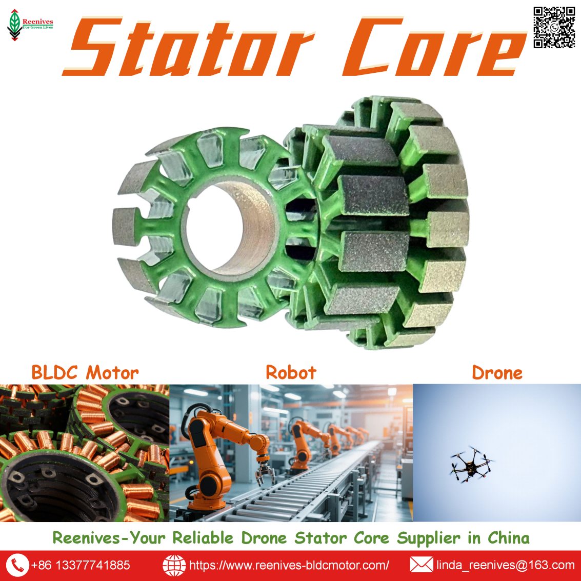
Hairpin winding stator core — rectangular slot geometry with copper hairpin conductors, manufactured by Reenives with imported high-speed stamping lines.
Types of Hairpin Winding
Hairpin winding configurations vary by hairpin shape, layer count, and connection method. The main types are:
- Single-Layer Hairpin Winding — One hairpin per slot, simpler insertion and welding, lower slot fill than multi-layer designs. Used in smaller motors and cost-sensitive applications.
- Double-Layer Hairpin Winding — Two hairpins per slot (four conductor legs), the most common configuration in automotive traction motors. Balances slot fill, AC loss, and manufacturability.
- Four-Layer Hairpin Winding — Four hairpins per slot, higher slot fill and lower resistance, at the cost of more complex welding and higher AC losses.
- Continuous Hairpin (Wave) Winding — Hairpins are formed as continuous wave shapes rather than separate U-bars, reducing the number of weld joints.
- I-Pin / Bar Winding — Individual straight bars inserted and welded at both ends, a variant used where hairpin bending is impractical.
- Segmented Hairpin Winding — Hairpins inserted into segmented stator teeth, then assembled into a full ring. Improves winding access and slot fill.
- Round-Wire Winding (for comparison) — Conventional wound copper wire, lower slot fill but simpler tooling and lower AC loss at high frequency.
For most drone, eVTOL, and high-performance BLDC motor designs, double-layer hairpin winding is the starting point — it offers a strong balance of slot fill, thermal performance, and production feasibility.
Key Specifications & Data
Below are typical specifications for stator cores intended for hairpin winding, alongside conventional round-wire stators for comparison. Custom values are available upon request.
| Parameter | Hairpin Winding Stator | Round-Wire Stator | Notes |
|---|---|---|---|
| Slot Fill Factor | 70% – 80% | 40% – 50% | Copper cross-section / slot area |
| Conductor Type | Rectangular copper bar | Round copper wire | Hairpin requires rectangular section |
| Slot Shape | Rectangular, sharp corners | Trapezoidal / rounded | Critical for hairpin insertion |
| Slot Width Tolerance | ±0.03 mm – ±0.05 mm | ±0.05 mm | Tighter for consistent insertion |
| Slot Corner Radius | Small, controlled | Larger, less critical | Prevents insulation damage |
| Burr Height (Slot Area) | ≤ 0.02 mm – 0.03 mm | ≤ 0.03 mm | Burrs cut hairpin insulation |
| Lamination Material | Silicon steel (20JNEH1200, 35WW250) | Silicon steel (35WW250, 50WW470) | Low core loss grades |
| Lamination Thickness | 0.20 mm – 0.35 mm | 0.20 mm – 0.50 mm | Thinner = lower eddy current loss |
| Insulation Coating | Epoxy powder, H-Class 180°C | Epoxy powder, H-Class 180°C | Must withstand insertion abrasion |
| Core Loss (at 400Hz, 1T) | ≤ 25 W/kg | ≤ 25 W/kg | Material dependent |
| Dimensional Tolerance | ±0.05 mm (critical dimensions) | ±0.05 mm | High-precision stamping |
| Stacking Factor | ≥ 95% | ≥ 95% | Minimizes air gaps |
| Weld Joint Count | High (one per hairpin end) | None | Drives welding capex and cycle time |
Data source: Reenives internal testing, industry hairpin winding design references, and supplier material datasheets, 2024–2025. Actual values may vary by design.
Applications & Why Hairpin Winding Is Used
Hairpin winding is chosen where slot fill, power density, and thermal performance matter more than tooling simplicity. Here is where it delivers real value:
- High-Power UAV & eVTOL Motors — Larger UAV and eVTOL propulsion motors benefit from higher slot fill, which means more torque from the same motor envelope and better heat rejection during climb and hover.
- Heavy-Lift Drone Motors — Agricultural and industrial drones carrying heavy payloads need continuous torque without thermal throttling. Hairpin winding improves copper utilization and reduces I²R heating.
- Electric Vehicle Traction Motors — The largest current application for hairpin winding, driven by power density and automated manufacturing.
- High-Efficiency Generators — UAV onboard generators and portable power units benefit from lower resistance and improved thermal margin.
- Industrial Servo & Robotics Motors — Where torque density and repeatability are critical.
- Gimbal & Stabilization Motors — Where smooth torque and precise control matter, though AC loss considerations apply.
Reenives stator cores are used in hairpin winding projects across drone, eVTOL, industrial, and automotive applications — supplying the lamination stack and slot geometry that hairpin insertion depends on.

Hairpin winding stator cores from Reenives are used in high-power UAV, eVTOL, and BLDC motor projects where slot fill and thermal performance are critical.
How to Select the Right Stator Core for Hairpin Winding
Hairpin winding places specific demands on the stator core. If you are evaluating a stator core for hairpin insertion, work through these steps:
- Confirm the Winding Architecture — Single-layer, double-layer, or four-layer? This determines the number of conductor legs per slot and the required slot depth and width.
- Define Slot Geometry for the Hairpin — The slot must be rectangular with controlled corner radius, sized to the hairpin cross-section plus insulation and insertion clearance. This is the most critical stator core specification.
- Tighten Slot Width Tolerance — Hairpin insertion demands tighter slot width tolerance than round wire, typically ±0.03 mm to ±0.05 mm. Loose slots cause vibration and poor thermal contact; tight slots damage insulation during insertion.
- Control Burr Height in the Slot Area — Burrs on slot edges will cut hairpin insulation during insertion. Specify ≤ 0.02–0.03 mm burr height and verify with incoming inspection.
- Select Lamination Thickness — For high-frequency operation, 0.20 mm laminations reduce eddy current loss. For lower-frequency, higher-torque designs, 0.35 mm may be acceptable.
- Specify Epoxy Coating for Insertion Abrasion — The lamination coating must withstand mechanical abrasion from hairpin insertion. H-Class 180°C electrostatic epoxy coating is recommended.
- Plan for End-Winding and Welding Access — Stator core stack length and end-plate design must leave room for hairpin bending and welding tooling.
- Request Samples & Test — Reenives provides free stator core samples for qualified hairpin projects. Validate slot fit, insertion force, and coating integrity before committing to production.
FAQ — Hairpin Winding & Stator Core Parameters
Q1: What is hairpin winding on a stator?
A: Hairpin winding is a stator winding technique where pre-formed rectangular copper conductors, bent into a U or hairpin shape, are inserted into the stator slots from one end. The straight legs fill the slot, and the open ends at the opposite side are twisted and welded to form the winding circuit. Because rectangular conductors pack more efficiently than round wire, hairpin winding typically achieves a slot fill factor of 70–80%, compared with roughly 40–50% for conventional round-wire winding.
Source: Reenives engineering team, based on hairpin winding design principles.
Q2: What slot shape and tolerance does hairpin winding require from the stator core?
A: Hairpin winding requires a rectangular slot profile with sharp, controlled corner radii, sized to the hairpin cross-section plus insulation and insertion clearance. Slot width tolerance should typically be ±0.03 mm to ±0.05 mm — tighter than for round wire. Burr height in the slot area should be ≤ 0.02–0.03 mm, because burrs will cut the hairpin insulation during insertion. The lamination coating should also be abrasion-resistant, which is why H-Class 180°C electrostatic epoxy coating is recommended.
Source: Reenives engineering team, based on hairpin winding process requirements.
Q3: What is the advantage of hairpin winding over round-wire winding?
A: The main advantage is a much higher slot fill factor — typically 70–80% for hairpin versus 40–50% for round wire. This means more copper cross-section in the same slot, which lowers DC resistance, increases power density, improves thermal performance, and enables automated insertion and welding for better production repeatability. The trade-offs are higher AC losses at very high electrical frequencies, more complex welding, and much stricter stator slot geometry requirements.
Source: Reenives engineering team, based on hairpin winding design references.
Q4: Is hairpin winding suitable for high-RPM drone motors?
A: Hairpin winding is most valuable in larger, higher-power drone and eVTOL motors where slot fill, torque density, and thermal performance are the limiting factors. For very small, very high-RPM FPV motors, the high electrical frequency increases AC losses in large rectangular conductors, so round wire or subdivided conductors may remain preferable. The choice depends on the motor's electrical frequency, power level, and cooling strategy.
Source: Reenives engineering team, based on motor design principles.
Q5: What lamination thickness and material do you recommend for hairpin winding stator cores?
A: For high-frequency operation, we recommend 0.20 mm silicon steel laminations in low-loss grades such as 20JNEH1200 or 35WW250. For lower-frequency, higher-torque designs, 0.35 mm laminations may be acceptable. Core loss for our standard stator cores is typically ≤ 25 W/kg at 400Hz and 1 Tesla, with premium materials achieving lower values.
Source: Reenives internal testing data and material datasheets, 2024.
Q6: Can you develop custom stator cores for hairpin winding applications?
A: Yes. We support private mould development for hairpin winding stator cores. Provide us with your required stator outer diameter, stator bore, stack length, slot number, slot width and depth, corner radius, lamination thickness, and material grade. Our R&D team will design and produce custom stator cores tailored to your hairpin winding process. Tooling lead time is typically 15–25 days.
Source: Reenives custom development process.
Summary — Hairpin Winding Starts with the Right Stator Core
Need Precision Stator Cores for Your Hairpin Winding Project?
Hairpin winding can deliver 70–80% slot fill and significantly better thermal performance — but only if the stator core is designed for rectangular conductors from the start. Reenives supplies precision stator cores with the rectangular slot geometry, tight tolerances, and abrasion-resistant coating that hairpin insertion demands.
📦 Bulk purchasing · 🔧 Private mould development · 🧪 Free samples
🌐 Official Website: www.reenives-bldcmotor.com
📧 Email: linda_reenives@163.com
Contact us now for a free stator core sample and tailored solution for your hairpin winding project.
Dongguan Runlu Motor Technology Co., Ltd.
Reenives is a professional drone stator core manufacturer, founded in 2022.
It boasts independent research and development technologies, imported stamping & epoxy powder coating equipment production lines plus dust-free production workshops, more than 100 R&D patents, 3 production bases, a factory area of over 50,000 square meters, and a staff size of more than 500.
From production to sales, we support bulk purchasing, private mould develop, and samples making, and can provide tailor-made perfect solutions for your production and usage scenarios. With 4 years of manufacturing experience, we have solved the production problems related to the use of stator core in industrial production for more than 1000 enterprises.
We can ship globally (with complete export qualifications). Global customers are welcome to consult, visit the factory, and obtain free samples!
Reenives Runlu Motor Hairpin Winding Stator Core
What is AC Generator Stator?
What is Cycle Electric Stator?
Related Article