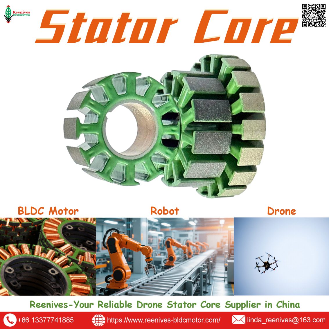
What is DC Generator Stator?

DC Generator Stator — What the Generator Core Teaches About Drone BLDC Thermal Limits, and Where That Knowledge Stops
A drone motor that loses thrust after ten minutes of hover is rarely a propeller problem or an ESC problem. It is a DC generator stator problem in the sense that matters: the stationary laminated core inside the motor was designed with assumptions inherited from conventional DC machine practice — assumptions about lamination thickness, flux density, and duty cycle that were never valid for a UAV propulsion motor running at 400–1,500 Hz electrical frequency inside a 12-gram thermal envelope. The DC generator stator is the stationary element of a DC machine, built as salient poles with field coils wound around laminated pole cores, historically using 0.4–0.6 mm steel laminations. That construction works because a DC generator runs at fixed speed and moderate frequency, and its stator carries the field, not the armature. A drone BLDC stator looks structurally similar — laminated steel with copper windings — but it carries the three-phase armature winding, operates at electrical frequencies 5–20 times higher than industrial machines, and has almost no thermal mass to absorb loss. This guide is for engineers and B2B buyers who need to understand what carries over from DC generator stator practice to drone BLDC stator specification, what does not, and how to specify a core that holds continuous hover rather than cooking its insulation.
Table of Contents
- What Is a DC Generator Stator?
- Salient-Pole Field Stator vs. Distributed Armature Stator: What Changes in a Drone BLDC
- Parameters That Separate a Usable Drone Stator from a Generator-Derived Liability
- Where DC Generator Stator Heritage Shows Up — and Fails — in UAV Propulsion
- Selection Checklist: Five Steps Before You Approve a Drone Stator Core Spec
- FAQ: DC Generator Stator and Drone BLDC Procurement Questions
- Summary & CTA
What Is a DC Generator Stator?
A DC generator stator is the stationary magnetic structure of a direct-current generator. In a conventional DC machine, the stator consists of a yoke and salient field poles — laminated steel cores with field coils wound around them — whose function is to produce the magnetic field through which the rotating armature passes. The laminations exist to interrupt eddy-current paths through the pole core, and historical DC machine practice uses pole-core laminations in the 0.4–0.6 mm range. The armature — the winding in which voltage is actually induced — sits on the rotor, and a commutator mechanically rectifies the AC developed in the armature coils into DC at the terminals.
That architecture is inverted in a drone BLDC motor. In a BLDC outrunner, the permanent magnets are on the rotating bell, and the three-phase copper windings are on the stationary stator. There is no field winding on the stator and no commutator. The stator carries the armature winding, and the ESC performs electronic commutation from the DC bus. The structural resemblance — laminated steel with copper — hides a fundamental functional difference:
| Functional Role | DC Generator Stator | Drone BLDC Stator |
|---|---|---|
| What the stator carries | Field winding (produces the magnetic field) | Three-phase armature winding (produces torque) |
| Where the active winding sits | Rotor (armature) | Stator |
| Commutation | Mechanical commutator and brushes | Electronic, via ESC |
| Typical lamination thickness | 0.4–0.6 mm pole-core laminations | 0.20 mm or 0.10 mm for high-RPM drone motors |
| Electrical frequency regime | Power frequency or low harmonic content | 400–1,500 Hz depending on pole count and RPM |
| Thermal mass context | Cast frame and yoke provide heat capacity | Stator body is the primary heat reservoir; minimal housing mass |
The practical consequence: a drone BLDC stator is not a scaled-down DC generator stator with magnets added. It is a component that inherited lamination-based construction from DC machine practice but operates under thermal and frequency conditions that make conventional generator lamination thickness a liability, not a baseline.
Salient-Pole Field Stator vs. Distributed Armature Stator: What Changes in a Drone BLDC
The classification of DC machine stators begins with saliency. A salient-pole stator has projecting poles with concentrated field coils around each pole body — the classic DC generator and DC motor field structure. The poles are discrete, the field winding is DC, and the flux path is intentionally non-uniform around the circumference because that is what a DC machine field requires. In a drone BLDC stator, the saliency story is different. The stator has teeth, but those teeth carry a three-phase armature winding distributed or concentrated around the circumference to produce a rotating MMF, not a stationary field. The two dominant drone BLDC stator winding architectures are:
Concentrated windings place each coil around a single tooth. Drone motors are overwhelmingly built this way — the 12-slot/14-pole (12N14P) outrunner with concentrated fractional-slot windings is the default configuration for multirotor propulsion. Concentrated windings minimize end-winding volume, shorten copper length, and simplify automated production. The thermal trade-off is that loss is concentrated on the teeth, and there is less copper mass to spread heat laterally. In a drone stator with minimal thermal mass, tooth-body hot spots are the first failure location.
Distributed windings spread each phase across multiple slots per pole with coil pitch greater than one slot. The copper is distributed more evenly, producing more uniform heating — a classical advantage of distributed AC windings. The penalty is longer end windings and greater copper mass. Distributed windings enter drone specification when continuous current is high enough that tooth hot spots, not total copper loss, become the limiting factor.
The coreless (slotless) stator is the third architecture and the one furthest from DC generator heritage. Removing the iron core eliminates stator core loss entirely — the dominant limitation in high-frequency operation — and eliminates cogging torque, at the cost of lower torque density and a winding that relies entirely on potting and the stator body for heat extraction. A 9-slot/12-magnet coreless axial flux UAV propulsion motor achieved 89.5% system efficiency in ground testing, with the coreless design successfully reducing thermal buildup and magnetic losses compared to cored alternatives.
| Stator Architecture | Heritage | Drone Fit | Primary Thermal Consequence |
|---|---|---|---|
| Salient-pole field stator | DC generator / DC motor field | Not used for drone propulsion armature | Field winding loss on stator; no armature copper loss on stator |
| Concentrated armature, slotted | BLDC / PMSM practice | Default for multirotor hover and climb (12N14P) | Tooth-body hot spot; conduction path through teeth to housing |
| Distributed armature, slotted | AC machine practice | High-continuous-current UAV where uniform heat spreading justifies mass | More uniform heating; longer end windings and higher copper mass |
| Coreless / slotless | Axial flux and high-frequency PM machine practice | High-speed cruise, weight-critical platforms | Zero core loss; winding heat extraction depends entirely on potting |
For most 5-inch to heavy-lift multirotors, concentrated slotted remains the baseline. The DC generator salient-pole field stator is a reference architecture, not a template.
Parameters That Separate a Usable Drone Stator from a Generator-Derived Liability
Specifying a drone BLDC stator against DC generator stator assumptions fails on four parameters. The values below are drawn from supplier manufacturing specifications and published UAV stator design data — use them as a review baseline, not a substitute for prototype validation.
| Parameter | DC Generator Stator Baseline | Drone BLDC Stator Requirement | Consequence of Carrying Generator Baseline |
|---|---|---|---|
| Lamination thickness | 0.4–0.6 mm pole-core laminations | 0.20 mm baseline; 0.10 mm for high-RPM/premium | Severe eddy-current penalty at 400–1,500 Hz |
| Stacking factor | ≥ 0.95 conventional | ≥ 95% minimum; higher preferred for thin gauges | Low factor → higher current for same torque → added copper loss |
| Bore / air-gap tolerance | Generator clearance practice | ±0.05 mm critical dimensions; 0.2–1.0 mm air gap | Eccentric gap → flux loss, vibration, localized heating |
| Electrical frequency | Power frequency / low harmonic | 400–1,500 Hz typical; up to ~2,300 Hz at high RPM | 50/60 Hz loss data does not cover UAV operation |
Where DC Generator Stator Heritage Shows Up — and Fails — in UAV Propulsion
The DC generator stator heritage is visible in every drone stator core: laminated steel, slot geometry, and a yoke-pole-tooth magnetic circuit. But the operating envelope that made generator practice valid does not transfer. Three UAV duty profiles expose the gap.
Sustained hover and thermal steady state. In hover, current is roughly constant and the stator reaches thermal steady state within minutes. A stator built with generator-era lamination thickness heats continuously at hover electrical frequency before copper loss is even considered. The stator core is the primary thermal reservoir in a drone motor — there is no heavy cast frame to absorb heat — and a lossy core consumes the little thermal margin the motor has. Thin laminations and a high stacking factor are not performance refinements; they are the difference between a usable hover rating and a burst-only specification.
Throttle transients and burst ratings. A drone motor’s “max current” label is usually time-limited. Copper loss is quadratic in current, and the stator’s thermal mass determines whether the next burst begins from an already-elevated baseline. A core with high iron loss has less headroom to absorb the copper-loss transient because it is already generating heat passively at every RPM.
High-ambient and agricultural UAV duty. Agricultural spraying and inspection platforms operate above 35°C ambient, where the stator-to-ambient delta shrinks. The same stator that holds insulation limits in a 25°C lab can exceed them in the field. Core loss at the operating point is part of that heat load, and generator-era loss data at 50 Hz does not tell you what that load is.
The generator connection is not only historical. DC generator stator principles re-enter UAV design when the propulsion motor is used as a starter-generator or when an on-board generator is driven by the propulsion system. In those roles, the machine must produce DC power as well as thrust, and the stator winding must serve both motoring and generating functions across the flight envelope. The thermal and magnetic requirements become more demanding, not less, and the lamination and tolerance specifications that support continuous hover also support the generating mode.
Selection Checklist: Five Steps Before You Approve a Drone Stator Core Spec
- Stop specifying against DC generator lamination practice. The 0.4–0.6 mm thickness that is reasonable for a salient-pole field core at power frequency is a thermal liability at UAV electrical frequencies. Start with 0.20 mm NGO silicon steel as the drone baseline, and step to 0.10 mm only when the efficiency gain at your maximum continuous RPM justifies the stamping and stacking-factor penalties.
- Calculate electrical frequency at maximum continuous RPM and demand loss data at that frequency. Use fe = RPM × (poles/2) / 60. A 12N14P motor at 15,000 rpm runs at approximately 1,750 Hz. If a supplier provides only 50/60 Hz Epstein loss data or generic “low core loss” claims, the stator is not specified for UAV duty. Require W/kg iron-loss data at the actual operating frequency and flux density.
- Specify stacking factor alongside thickness. A 0.20 mm lamination with a poor stacking factor gives back much of its eddy-current advantage through reduced effective magnetic steel. Require ≥ 95% stacking factor as a minimum for thin drone laminations, and confirm the measurement method and lot-level traceability of thickness tolerance — ±0.005 mm on incoming coils is a reasonable supplier control point.
- Match bore, air gap, and concentricity to the rotor as a single system. Require ±0.05 mm on critical stator dimensions, a defined air-gap budget (0.2–1.0 mm for drone motors), and air-gap concentricity data (TIR) in PPAP documentation. For segmented stator cores, confirm concentricity < 0.03 mm if the design depends on it for torque smoothness. The stator and rotor form one magnetic circuit; a stator specified in isolation from rotor OD tolerance is a specification with a hole in it.
- Validate hot-spot temperature in the actual mounting and airflow condition. A thermistor on the core or a thermal camera reading on the motor bell does not give the winding hot-spot temperature. Require winding resistance-based hot-spot estimation or embedded thermocouple data at continuous current in the worst-case ambient. The acceptance criterion is hot-spot temperature within the insulation class after thermal steady state — not a calculated efficiency and not an averaged case temperature.
FAQ: DC Generator Stator and Drone BLDC Procurement Questions
Q1: Can I use DC generator stator lamination thickness — 0.4 to 0.6 mm — for a drone BLDC motor?
No. DC generator pole cores at 0.4–0.6 mm are acceptable at power frequency, but drone motors operate at 400–1,500 Hz electrical frequency, and eddy-current loss scales with the square of both thickness and frequency. At UAV frequencies, 0.4–0.6 mm laminations generate eddy-current loss that dominates the thermal budget. Drone BLDC stators should start at 0.20 mm NGO silicon steel, with 0.10 mm reserved for high-RPM or efficiency-critical platforms where the stamping and stacking-factor penalties are justified.
Q2: What stacking factor should I specify for a drone stator core, and why is ≥ 95% the baseline?
Stacking factor is the steel fraction of total stack volume. Conventional lamination specifications sit at ≥ 0.95, and Reenives drone BLDC stator specifications list ≥ 95% as the baseline. A lower factor means less effective magnetic steel for the same stack height, which increases reluctance, forces higher current for the same torque, and adds copper loss to the thermal load. For 0.10 mm laminations, stacking factor may drop to around 0.93 because of the higher proportion of inter-lamination insulation — that is a design trade-off to model, not a default to accept.
Q3: What air gap and tolerance should I specify between a drone stator and rotor?
For drone brushless stators, specify ±0.05 mm on critical bore and rotor outer diameter dimensions, a 0.2–1.0 mm air-gap range depending on motor size and rotor design, and air-gap concentricity (TIR) of 0.03–0.08 mm depending on size. For segmented stator cores where the design depends on tight concentricity for torque smoothness, < 0.03 mm is achievable. A smaller gap increases flux and torque density but demands tighter concentricity and bearing stiffness; a larger gap tolerates variation but reduces flux and increases current for the same torque.
Q4: Does a coreless stator eliminate the DC generator stator lamination problem entirely?
A coreless stator removes the iron core, and with it stator core loss — the dominant limitation in high-frequency operation. A 9-slot/12-magnet coreless axial flux UAV motor achieved 89.5% system efficiency and reduced thermal buildup and magnetic losses in ground testing. But coreless is not a universal replacement. It has lower torque density, relies entirely on potting for winding heat extraction, and is best suited to high-speed cruise and weight-critical platforms rather than sustained hover where torque density dominates. For most multirotor propulsion, a thin-lamination slotted stator remains the appropriate architecture.
Q5: What production data should I demand to verify a stator supplier’s iron-loss claim for a drone motor?
Require W/kg iron-loss data at the electrical frequency corresponding to your maximum continuous RPM, not at 50/60 Hz. For a 12N14P motor at 15,000 rpm, that frequency is approximately 1,750 Hz. Also require lot-level incoming material data: thickness tolerance (±0.005 mm), Epstein loss at a stated frequency and flux density (400 Hz / 1.0 T is a common reference), and surface insulation resistance before stamping. If the supplier can only provide power-frequency loss data, the claim does not cover UAV operating conditions and cannot be used for thermal sizing.
Summary & CTA
A DC generator stator teaches the right structural vocabulary — laminations interrupt eddy currents, stacked steel carries flux, and the stationary core is a magnetic component, not a spacer. But it teaches the wrong operating assumptions for drone BLDC propulsion. The 0.4–0.6 mm pole-core laminations and power-frequency loss data that make a DC generator stator valid become a thermal liability at 400–1,500 Hz inside a 12-gram stator with minimal thermal mass. A drone stator core needs 0.20 mm baseline laminations, ≥ 95% stacking factor, ±0.05 mm critical tolerances, and iron-loss data at the frequency the motor actually runs at. If you are translating DC machine experience into a UAV stator specification, or qualifying a stator core for a platform where hover must last longer than a burst rating, bring us your continuous current, maximum RPM, slot/pole combination, and air-gap budget.
Reenives — Drone Motor Stator Core One-Stop Solution Supplier
🌐 Website: www.reenives-bldcmotor.com
📱 WhatsApp: +86-13377741885
✉️ Email: linda_reenives@163.com
Send your stator dimensions, continuous current, maximum RPM, and air-gap target — we will return a stator core proposal with lamination thickness, stacking factor, bore tolerance, and a thermal validation plan aligned with your duty cycle.
Dongguan Runlu Motor Technology Co., Ltd.
About Reenives
Reenives is a professional drone stator core manufacturer, founded in 2022. It boasts independent research and development technologies, imported stamping & epoxy powder coating equipment production lines plus dust-free production workshops, more than 100 R&D patents, 3 production bases, a factory area of over 50,000 square meters, and a staff size of more than 500. From production to sales, we support bulk purchasing, private mould develop, and samples making, and can provide tailor-made perfect solutions for your production and usage scenarios. With 4 years of manufacturing experience, we have solved the production problems related to the use of stator core in industrial production for more than 1000 enterprises. We can ship globally (with complete export qualifications). Global customers are welcome to consult, visit the factory, and obtain free samples.
Social & Discoverability: Reenives / Dongguan Runlu Motor Technology Co., Ltd. — search for “Reenives drone stator core” and “Reenives DC generator stator” on LinkedIn and Google to verify our manufacturing footprint, thin-lamination capability, and UAV stator core case references.
What is Motor and Stator?
Related Article