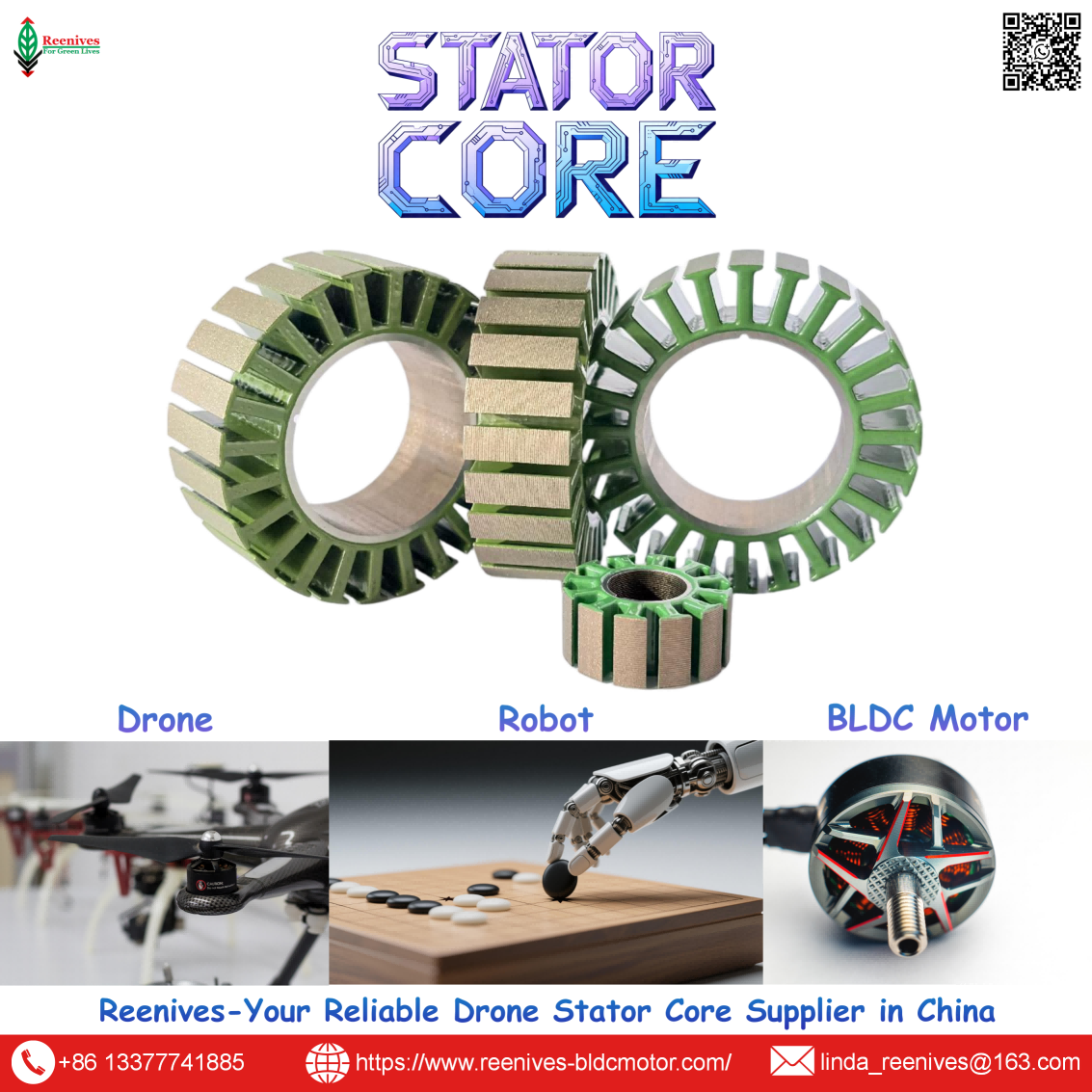
What is Brushless Motor Drone?

What is a Brushless Motor Drone? The BLDC Motor That Defines Thrust, Endurance, and Thermal Margin
Most brushless motor drone problems are not flight-controller tuning problems and not propeller problems. They are motor specification problems that were locked in before the first flight. The quad hovers, but the motors run hot. Endurance falls short of the battery calculation. Thrust sags after a few minutes of aggressive flying. The ESC logs show current spikes that do not match the bench data. In almost every case, the root cause sits in the brushless motor’s electromagnetic design — specifically in the stator core that converts electrical input into magnetic flux, and in the KV rating that decides how that flux is traded for RPM versus torque.
A brushless motor drone is defined by its propulsion motors, and those motors are not commodity parts. Published data shows brushless efficiency at 85–92% versus roughly 60–75% for brushed motors. The same published sources show that KV is a torque-speed trade, not a quality score: high KV (2000–4000+) suits small propellers and racing, low KV (300–1000) suits large propellers and heavy-lift, and mismatching the two causes either low thrust or excessive current draw. And the stator core underneath all of that has a measurable loss profile: 0.20 mm laminations at roughly 10–14 W/kg at 1.0 T / 400 Hz, versus 0.35 mm laminations at roughly 28–35 W/kg — a difference that becomes winding temperature and lost flight time at drone operating frequencies.
This guide answers the long-tail question at the level a propulsion engineer or procurement lead needs: the BLDC definition and how the motor produces thrust, the KV and slot-pole families that define drone motor behavior, the published core-loss and thermal parameters with their standards, the mission profiles where each specification binds, and a five-step selection workflow that turns a motor datasheet into a purchase specification. Every figure below is traceable to a published source or a named measurement standard.
In this guide — jump to the section your project needs:
- What Is a Brushless Motor Drone? The BLDC Definition and the Energy-Conversion Chain
- Brushless Motor Configurations for Drones: Outrunner, Inrunner, and 12N14P Slot-Pole Families
- Published Parameters: KV, Thrust-to-Weight, Iron Loss, Lamination Thickness, and Stator Core Specifications
- Application Profiles: Which Motor Parameter Binds Which Drone Mission
- A 5-Step Brushless Motor Selection Workflow for Drone Platforms
- FAQ: Definition, KV, 12N14P, Lamination Thickness, Overheating, and Stator Core Specifications
- Summary: Specify the Motor, Not Just the Frame
What Is a Brushless Motor Drone? The BLDC Definition and the Energy-Conversion Chain
A brushless motor drone is an unmanned aircraft whose propulsion comes from brushless DC (BLDC) motors. The defining difference from a brushed motor is the commutation method: a brushed motor uses a mechanical commutator and brushes to switch current in the rotating armature, while a BLDC motor uses an external electronic speed controller (ESC) to switch current through stationary stator windings in the correct sequence. Published descriptions put it simply: the ESC switches current through the three stator windings in sequence, creating a rotating magnetic field that pulls the rotor magnets around, and because there is no physical contact between rotating and stationary parts, there is no brush wear, efficiency is much higher (85–92% versus roughly 60–75%), and the motor can reach much higher RPM.
The energy-conversion chain is the definition in motion. The battery supplies DC power. The ESC commutates that DC into three-phase AC-like current in the stator windings. The stator’s windings and laminated core create a rotating magnetic field. The rotor’s permanent magnets are pulled by that field, producing torque. The rotor drives the propeller directly in an outrunner configuration, and the propeller accelerates air to produce thrust. Every stage has a loss, and the two that matter most for a drone’s endurance are copper loss in the windings and iron loss in the stator core. Copper loss is set by winding resistance and current; iron loss is set by the core’s lamination thickness and the electrical frequency the motor runs at.
That last point is where the brushless motor drone definition becomes a specification problem. Electrical frequency is not the mechanical RPM; it is RPM multiplied by pole pairs. A 14-pole motor at 15,000 RPM runs at an electrical frequency of 1,750 Hz, and at that frequency the eddy-current penalty for thick laminations is severe. The motor that looks adequate on a 50 Hz bench test can underperform in the air, because the air is where the frequency is high and the core loss becomes heat.
Procurement translation: “brushless motor drone” describes the propulsion architecture, not the performance level. Two drones can both be brushless and have very different endurance, thermal margin, and thrust consistency, because the BLDC category contains a wide range of KV ratings, stator geometries, lamination grades, and magnet specifications. The specification must name the motor-level parameters — KV, slot-pole, stator core grade and thickness, and the operating point — not the architecture label alone.
Brushless Motor Configurations for Drones: Outrunner, Inrunner, and 12N14P Slot-Pole Families
Brushless drone motors are classified along two axes that matter for selection: the rotor topology (outrunner versus inrunner) and the slot-pole combination inside the stator.
Outrunner versus inrunner
| Topology | Construction | Torque / Speed Character | Drone Role |
|---|---|---|---|
| Outrunner | External bell with magnets rotates around an internal stator | Higher torque at lower RPM; direct propeller mounting | Dominant for multirotor propulsion and direct-drive propellers |
| Inrunner | Rotor spins inside the stator | Lower inertia, faster dynamic response, higher speed capability | Gimbals and auxiliary motion functions where fast response matters |
The outrunner’s dominance in propulsion is not a preference; it is a consequence of the torque-speed requirement. A multirotor propeller needs relatively high torque at moderate RPM, and an outrunner’s larger diameter produces that torque without a gearbox. Published UAV motor selection guidance describes outer-rotor designs as the dominant approach for propulsion, pairing high torque at relatively low speeds with straightforward mechanical integration via direct propeller mounting. Inner-rotor motors are positioned as a better fit for gimbals and auxiliary functions where lower inertia and fast dynamic response matter.
Slot-pole families: 12N14P and its alternatives
The slot-pole combination defines the electromagnetic structure inside the motor. A 12N14P motor has 12 stator slots and 14 rotor poles, and it is one of the most common outrunner configurations for drone and higher-torque applications. The slot count is divisible by three for balanced three-phase operation, and the unequal slot-to-pole ratio reduces cogging torque. The concentrated winding pattern commonly used with 12N14P is ABCABCABCABC.
| Slot-Pole | Slots | Poles | Character | Typical Drone Fit |
|---|---|---|---|---|
| 12N14P | 12 | 14 | Higher torque, low cogging, concentrated winding | FPV and multirotor propulsion; the workhorse configuration |
| 9N12P | 9 | 12 | Lightweight, higher speed bias | Small outrunners and lightweight builds |
| 24N20P / 18N16P | 24 / 18 | 20 / 16 | More slots, different torque-ripple profile | Larger outrunners and specific industrial platforms |
| 12N10P | 12 | 10 | Alternative pole count, different cogging signature | Selected where the 12N14P profile does not match the application |
Sources: Published outrunner slot-pole lists (9N6P, 9N12P, 12N8P, 12N10P, 12N14P, 18N16P, 24N20P); 12N14P described as common for higher-torque applications with ABCABCABC winding.
The practical selection rule is that 12N14P is the default for drone propulsion because it balances torque, cogging, and winding manufacturability. Other combinations are not upgrades or downgrades; they are different trade-offs. A 9N12P motor may be lighter and better suited to a small propeller; a 24-slot stator may be chosen for a larger outrunner where a different torque-ripple profile is acceptable. The slot-pole count must be matched to the stator core geometry and the rotor pole count, which is why a “12-slot stator” without a specified pole count is an incomplete specification.
Published Parameters: KV, Thrust-to-Weight, Iron Loss, Lamination Thickness, and Stator Core Specifications
KV and the torque-speed trade
KV is the motor’s velocity constant — RPM per volt under no load — and the formula is RPM = KV × Voltage. For the same motor size, higher KV means more RPM but less torque; lower KV means more torque but lower RPM. Published ranges place high KV at 2000–4000+ (small propellers, racing, snappy response), low KV at 300–1000 (large propellers, heavy-lift, long-range), and mid KV at 1000–2000 as the sweet spot for 5-inch freestyle. The matching rule is equally published: pair high KV with small-diameter propellers and low KV with large-diameter propellers; mismatching causes either very little thrust or excessive current draw and overheating.
Stator dimensions and thrust-to-weight
Motor names such as 2207 or 2306 encode stator dimensions: the first two digits are stator diameter in millimeters, the last two are stack height. A taller stator means more copper volume, more torque, and more power handling, but also more weight. Published UAV motor selection guidance frames propulsion sizing around the thrust-to-weight ratio required to lift the payload and airframe while accounting for motor self-weight, and stresses that efficiency is inseparable from mission duration. Efficiency is measured in grams of thrust per watt: 3–5 g/W is inefficient, 6–8 g/W is average freestyle/cinematic, and 10–15 g/W is an efficient long-range cruise build.
Lamination thickness and iron loss: the stator-core parameter that decides heat
Iron loss has two components: hysteresis loss, proportional to frequency and the grade’s coercivity, and eddy-current loss, proportional to the square of both lamination thickness and frequency. In a 50 Hz industrial motor, thick laminations are tolerable. In a drone motor at 15,000 RPM, the electrical frequency is far higher and the eddy-current penalty becomes severe. Published comparison data is direct:
| Thickness | Typical Grade | Iron Loss @ 1.0 T / 400 Hz | Best Fit | Relative Cost |
|---|---|---|---|---|
| 0.35 mm | 35W300 / 35W270 | ~28–35 W/kg | Industrial servo ≤3,000 RPM, low-speed torque motors | Low |
| 0.27 mm | 27W230 / 27W250 | ~18–24 W/kg | Mid-speed servo 3,000–8,000 RPM, robot joints | Medium |
| 0.20 mm | 20W1200H / 20W1500H | ~10–14 W/kg | High-speed ≥8,000 RPM, UAV, frameless motors | High |
Source: HIMAGNET, “Silicon Steel Thickness and Iron Loss: Selecting 0.20mm vs 0.35mm for Small Motors,” 2026.
The motor-level consequence is thermal. A 60 W motor core with 0.35 mm laminations generating 8 W of iron loss at operating speed drops to approximately 2.5 W with 0.20 mm laminations — a 5.5 W saving that reduces steady-state winding temperature by an estimated 15–25°C, allows approximately 8–12% higher continuous torque before the thermal limit, and extends service life by reducing thermal cycling stress. In a drone, that thermal margin is the difference between a hover that holds its thrust curve and one that sags as the winding heats and resistance rises.
Stator core specifications that carry the loss performance
A stator core specification must name the measurement standard, not just the loss number. IEC 60404-2 defines the Epstein-frame method for specific total loss of electrical steel, with the conditions that the polarization waveform be sinusoidal, the measurement temperature be 23°C ±5°C, and no external stress be exerted on the specimen. That last condition is why a finished-stack report matters more than a mill certificate: stamping and stacking introduce stress and burrs that the Epstein specimen does not experience.
Reenives publishes 0.20 mm grade performance measured per IEC 60404-2 and GB/T 3655-2022: core loss ≤9.6 W/kg (typical 9.2 W/kg) at 1.0 T / 400 Hz, magnetic flux density B50 ≥1.69 T, thickness 0.20 mm ±0.008 mm, C5 epoxy insulation at >1400 V dielectric strength per ASTM D149, burr height ≤0.03 mm, and operating temperature −40°C to 180°C (short peak 200°C). For drone-grade cores, concentricity ≤0.02 mm keeps the air gap uniform, and interlocked or bonded stacking holds the stacking factor that preserves the flux density the lamination grade was selected to provide.
The datasheet-versus-field gap: a motor can use “0.20 mm electrical steel” and still underperform if the stack is loose, the burr height is uncontrolled, or the coating does not survive thermal cycling. The lamination grade sets the potential; the stator core manufacturing process determines how much of that potential reaches the installed motor. That is why the procurement specification must name finished-stack core loss, burr control, stacking factor, and concentricity — not just the steel grade.
Application Profiles: Which Motor Parameter Binds Which Drone Mission
| Drone Mission Class | Typical Motor / KV | Binding Parameter | Specification to Write |
|---|---|---|---|
| FPV racing / freestyle | High KV (2000–4000+) · 5-inch class | Iron loss at high electrical frequency; KV–propeller match | 0.20 mm low-loss stator grade; KV matched to prop diameter; core loss ≤9.6 W/kg @ 1.0 T / 400 Hz |
| Cinematic / long-range | Mid KV (1000–2000) · 5–7 inch | Efficiency (g/W) and thermal margin at cruise | 0.20 mm grade; efficiency curve above 85% at cruise; concentricity ≤0.02 mm for vibration control |
| Agricultural spraying | Low KV (90–150) · large propellers | Continuous thermal margin; coating durability | C5/C6 epoxy coating; 0.20 mm grade; finished-stack core loss report |
| Heavy-lift / logistics | Low KV (<100) · large diameter | Torque per amp and continuous thermal headroom | Stator volume and stacking factor; copper windings rated for continuous operation above 80°C; efficiency curve above 85% |
Source: Published drone motor selection ranges (KV by application, efficiency g/W, continuous operation above 80°C).
The pattern is that the binding parameter tracks the mission’s dominant loss mechanism. FPV racing binds on iron loss at high frequency and on the KV–propeller match, because a mismatch either starves thrust or overheats the motor. Cinematic and long-range bind on efficiency at cruise, because endurance is the product. Agricultural and heavy-lift bind on continuous thermal margin and coating durability, because the duty cycle is long and the environment is harsh. A motor specified only by KV has been specified on the variable that is easiest to quote and least sufficient to decide reliability.
A 5-Step Brushless Motor Selection Workflow for Drone Platforms
- Work backwards from thrust-to-weight, not forwards from a motor catalog. State the all-up weight, the number of motors, and the thrust-to-weight ratio the mission requires. Published UAV selection guidance emphasizes thrust output as the meaningful headline metric, with engineers working backwards from the ratio needed to lift payload and airframe while accounting for motor self-weight. A motor that looks efficient on a test stand can be undersized once the airframe and payload are included.
- Fix KV from the propeller diameter, then verify the efficiency at the cruise point. Use the published matching rule: high KV with small propellers, low KV with large propellers. Then check the efficiency curve at the throttle the mission actually uses. Published efficiency values are 6–8 g/W for average freestyle and 10–15 g/W for efficient long-range cruise. A motor that peaks at 10 g/W but cruises at 5 g/W is the wrong motor for an endurance platform.
- Specify the stator core grade and thickness against the electrical frequency, not the mechanical RPM. Calculate electrical frequency as RPM × pole pairs. For a 14-pole motor at 15,000 RPM, that is 1,750 Hz — well into the range where 0.35 mm laminations generate significant eddy-current loss. Specify 0.20 mm low-loss grade for high-frequency drone operation, and require core loss at a defined test point (1.0 T / 400 Hz) measured per IEC 60404-2 on the finished stack.
- Require the stator core manufacturing controls that preserve the grade’s potential. Name burr height (≤0.03 mm per Reenives specification), stacking factor, concentricity (≤0.02 mm for drone-grade cores), and coating class (C5 epoxy at >1400 V dielectric strength per ASTM D149). The lamination grade sets the loss ceiling; the stacking and burr control determine how much of that ceiling is achieved in the finished motor.
- Audit the motor-level test data at the operating point, not the catalog headline. Ask for the thrust table at the intended voltage and propeller, the efficiency curve across throttle, and the winding temperature at continuous cruise. A motor that passes a full-throttle burst test can still fail at cruise if the thermal design was validated only at peak power. Published guidance singles out thermal behavior under airflow cooling and bearing life as parameters that surface later in test programmes, especially as platforms move from hobby-grade assumptions into professional acceptance testing.
FAQ: Definition, KV, 12N14P, Lamination Thickness, Overheating, and Stator Core Specifications
What is a brushless motor drone, and how does the motor produce thrust?
A brushless motor drone is an unmanned aircraft whose propulsion comes from brushless DC (BLDC) motors rather than brushed motors. The BLDC motor has electromagnets on the stator and permanent magnets on the rotor. An electronic speed controller (ESC) switches current through the three stator windings in sequence, creating a rotating magnetic field that pulls the rotor magnets around. Because there is no physical contact between the rotating and stationary parts, there is no brush wear, efficiency is much higher than brushed motors (85–92% vs ~60–75%), and the motor can reach much higher RPM. That efficiency and RPM capability are why virtually all modern multirotor drones use brushless propulsion.
Source: Published BLDC motor operation and efficiency comparison for drone propulsion.
What does KV mean, and how does it affect drone performance?
KV is the motor’s velocity constant — the RPM the motor spins per volt of applied voltage under no load. The formula is RPM = KV × Voltage. For the same motor size, higher KV means more RPM but less torque; lower KV means more torque but lower RPM. High KV (2000–4000+) suits small propellers and racing drones; low KV (300–1000) suits large propellers, heavy-lift, and long-range builds; mid KV (1000–2000) is the sweet spot for 5-inch freestyle. The practical rule is to pair high KV with small diameter propellers and low KV with large diameter propellers — mismatching causes low thrust or excessive current draw.
Source: Published KV–thrust–efficiency selection guide.
What is the 12N14P configuration, and why is it common in drone motors?
12N14P means 12 stator slots (N) and 14 rotor poles (P). It is one of the most common outrunner configurations for drone and higher-torque applications. The slot count is divisible by three for balanced three-phase operation, and the unequal slot-to-pole ratio reduces cogging torque. A 12N14P stator typically uses a concentrated winding pattern such as ABCABCABCABC, and the combination is widely used in FPV and multirotor motors where a balance of torque, efficiency, and smoothness is required. Motor names such as 2207 or 2306 encode stator dimensions, not slot-pole count — the first two digits are stator diameter and the last two are stack height.
Source: Published outrunner slot-pole reference (12N14P common for higher-torque applications, ABCABCABC winding); motor naming convention.
How does lamination thickness affect a brushless drone motor?
Lamination thickness controls eddy-current loss, which scales with the square of both thickness and electrical frequency. In a small high-speed motor — a UAV motor at 15,000 RPM, for example — the electrical frequency is far higher than in a 50 Hz industrial motor, so the eddy-current penalty for thick laminations becomes severe. Published data shows 0.20 mm grades at roughly 10–14 W/kg at 1.0 T / 400 Hz, versus 0.35 mm grades at roughly 28–35 W/kg. Reenives publishes ≤9.6 W/kg (typical 9.2 W/kg) for its 0.20 mm grade at the same test point, measured per IEC 60404-2. In motor terms, switching from 0.35 mm to 0.20 mm reduces eddy-current loss by approximately 67% at the same flux density.
Source: HIMAGNET lamination comparison (0.20 mm vs 0.35 mm iron loss, ~67% eddy-current reduction); Reenives 0.20 mm grade specification.
Why does a brushless drone motor overheat or lose thrust over time?
Two failure paths dominate. The first is iron loss: thick laminations at high electrical frequency generate eddy currents that become heat in the stator, raising winding temperature and forcing the motor to derate before it reaches rated torque. A 60 W motor core with 0.35 mm laminations generating 8 W of iron loss can drop to approximately 2.5 W with 0.20 mm laminations — a 5.5 W saving that reduces steady-state winding temperature by an estimated 15–25°C and allows roughly 8–12% higher continuous torque before the thermal limit. The second is magnet demagnetization: a standard grade rated to ~80°C will lose field strength in a motor that runs hotter, producing unstable RPM and reduced thrust. Both are specification failures, not random defects.
Source: Published iron-loss thermal impact analysis (8 W → 2.5 W, 15–25°C reduction, 8–12% continuous torque gain); magnet temperature-class data from published NdFeB grade tables.
What stator core parameters should I specify for a brushless drone motor?
A complete stator core specification names the lamination thickness and grade (for example 0.20 mm low-loss non-grain-oriented silicon steel), the core loss at a defined test point measured per IEC 60404-2 on the finished stack, the stacking factor, the concentricity between stator bore and rotor outer diameter, and the insulation coating class. Reenives publishes 0.20 mm grade at ≤9.6 W/kg at 1.0 T / 400 Hz, concentricity ≤0.02 mm for drone-grade cores, and C5 epoxy coating with >1400 V dielectric strength per ASTM D149. These are the parameters that separate a stator that meets its thrust table in the field from one that meets it only on a datasheet.
Source: Reenives 0.20 mm laminated core specification (IEC 60404-2, ASTM D149, GB/T 3655-2022).
Summary: Specify the Motor, Not Just the Frame
What is a brushless motor drone? It is an aircraft whose thrust comes from electronically commutated BLDC motors — and the definition only becomes useful for procurement when it is expanded into the parameters that decide whether the aircraft hovers efficiently or overheats. KV sets the torque-speed trade; the slot-pole combination sets the electromagnetic structure; lamination thickness sets the iron loss at the electrical frequency the motor actually runs at; and the stator core manufacturing controls determine how much of the grade’s potential reaches the finished motor.
The published numbers are concrete. Brushless efficiency is 85–92% versus roughly 60–75% for brushed motors. KV ranges from 2000–4000+ for racing to 300–1000 for heavy-lift, with mid KV as the 5-inch freestyle sweet spot. Iron loss at 1.0 T / 400 Hz runs roughly 28–35 W/kg for 0.35 mm laminations and 10–14 W/kg for 0.20 mm, with Reenives publishing ≤9.6 W/kg for its grade measured per IEC 60404-2. And the 0.35 mm → 0.20 mm switch reduces eddy-current loss by approximately 67% at the same flux density, which becomes a 15–25°C winding temperature reduction and roughly 8–12% more continuous torque before the thermal limit.
The selection takeaway is that the motor is a system component, not a commodity line item. A drone platform that specifies KV but not the stator core grade, or the thrust table but not the thermal test condition, has left the endurance and reliability outcomes to the supplier’s default. The specification that prevents overheating and short flight time is the one that names the stator core’s finished-stack loss, the lamination thickness, the stacking factor, and the concentricity — because those are the parameters that turn a brushless motor into a brushless motor drone that holds its performance.
Sourcing stator cores for a brushless drone motor program?
Reenives manufactures precision laminated stator and rotor cores for brushless drone motors: 0.20 mm low-loss non-grain-oriented silicon steel, core loss ≤9.6 W/kg at 1.0 T / 400 Hz measured per IEC 60404-2, C5 epoxy coating at >1400 V dielectric strength per ASTM D149, concentricity ≤0.02 mm, and burr height ≤0.03 mm. Matched stator-rotor pairs, private mould development, and free samples are available for qualified drone and BLDC motor programs.
WhatsApp: +86-13377741885
Email: linda_reenives@163.com
Official website: www.reenives-bldcmotor.com
Dongguan Runlu Motor Technology Co., Ltd.
Reenives — Drone Motor One-Stop Solution Supplier
Reenives is a professional drone stator core manufacturer, founded in 2022. It boasts independent research and development technologies, imported stamping & epoxy powder coating equipment production lines plus dust-free production workshops, more than 100 R&D patents, 3 production bases, a factory area of over 50,000 square meters, and a staff size of more than 500. From production to sales, we support bulk purchasing, private mould development, and sample making, and can provide tailor-made perfect solutions for your production and usage scenarios. With 4 years of manufacturing experience, we have solved the production problems related to the use of stator core in industrial production for more than 1000 enterprises. We can ship globally (with complete export qualifications). Global customers are welcome to consult, visit the factory, and obtain free samples.
0.20 mm NO silicon steelCore loss ≤9.6 W/kg @ 1.0 T / 400 HzIEC 60404-2 verifiedC5 epoxy · >1400 VConcentricity ≤0.02 mmBurr ≤0.03 mmMatched stator + rotor pairsGlobal export qualifications
Reenives: Global Leading Drone Motor Parts Supplier
How to Do Drone Motor Winding?
Related Article