
How to Do Drone Motor Winding?
How to Do Drone Motor Winding: 12N14P Pattern, Wire Gauge, Turns, Tension, and the Tests That Catch a Bad Coil
A drone motor that runs but will not hold Kv, overheats at part throttle, or trips the ESC on a hard punch is usually not a magnet problem and not an ESC problem. It is a winding problem. The stator was wound with the wrong turn count for the target Kv, the wire gauge was chosen for fill rather than current, the tension drifted during the run, or a single tooth was wound in the wrong direction — and the motor still spins, which is exactly why the defect reaches the field. Winding is the one manufacturing step where a “working” motor can be a failed motor.
The published parameters show how narrow the window is. A 12N14P drone stator uses a fractional-slot concentrated winding with q = 12 ÷ (14 × 3) ≈ 0.286, an ABCABCABCABC pattern, and a fundamental winding factor of approximately 0.933. A KV900 stator carries 12 turns per phase (4 turns per slot) on 0.18–0.25 mm wire. Tension fluctuation must stay within ±0.05 N — tight enough to hold slot fill, loose enough not to thin the enamel. And the post-winding test must include surge (inter-turn) testing and three-phase current balance, because a resistance check alone will pass a coil that is already shorting between turns.
This guide answers the long-tail question at the level a motor engineer or procurement lead needs: the winding pattern and its variants, the turns–Kv–wire-gauge relationship, the tension and slot-fill parameters, the post-winding tests, the mission profiles where winding quality binds, and a five-step workflow for qualifying a wound stator. Every figure below is traceable to published winding machine specifications, FPV production data, or a named test standard.
In this guide — jump to the section your project needs:
- What Is Drone Motor Winding? The Four Variables That Decide Kv, Heat, and Reliability
- Winding Configurations: Concentrated, Distributed, and the 12N14P Pattern Variants
- Published Winding Parameters: Turns, Wire Gauge, Tension, Slot Fill, and Post-Winding Tests
- Application Profiles: Which Winding Parameter Binds Which Drone Mission
- A 5-Step Winding Qualification Workflow
- FAQ: Pattern, Turns, Wire Gauge, Tension, Slot Fill, and Winding Tests
- Summary: Wind to the Specification, Not to “It Spins”
What Is Drone Motor Winding? The Four Variables That Decide Kv, Heat, and Reliability
Drone motor winding is the process of placing enameled copper wire into the stator slots in a defined pattern, with a defined number of turns, using a defined wire gauge, under controlled tension. It is not a single operation but a set of four coupled variables, and each one moves a different performance parameter.
| Winding Variable | What It Sets | Published Drone Reference | Failure If Wrong |
|---|---|---|---|
| Winding pattern | Phase placement, winding factor, cogging profile | ABCABCABCABC for 12N14P; q ≈ 0.286; winding factor ≈ 0.933 | Phase imbalance, torque ripple, vibration, low Kv |
| Turns per slot | Kv and Kt (inverse relationship) | KV900 ≈ 12 turns/phase (4 turns/slot); FPV 2306: 12–14 turns/slot | Wrong Kv, wrong current draw, thermal overload |
| Wire gauge | Current capacity, resistance, copper loss | 0.18–0.25 mm single strand; 3×0.12–4×0.13 mm parallel; 0.40 mm sweet spot for 5-inch FPV | Overheating, voltage sag, low thrust at current |
| Tension | Slot fill consistency, enamel integrity, phase balance | ±0.05 N fluctuation; ±5 g fine-wire control; closed-loop dancer arm below 20 gf | Turn-to-turn short, loose coil, resistance imbalance |
Sources: Published 12N14P winding analysis (q = 0.286, winding factor 0.933); 3115 drone motor winding machine specification (0.18–0.25 mm wire, KV900 ≈ 12 turns/phase, tension ±5 g); FPV rewinding guide (12–14 turns/slot, 0.40 mm wire); closed-loop tension control data (±0.05 N, below 20 gf).
The reason these four variables belong together is that they trade against each other. Reducing turns raises Kv but also raises current draw and heat unless wire gauge is increased. Increasing wire gauge improves current capacity but reduces the number of turns that fit in the slot. Tightening tension improves slot fill but risks thinning the enamel and creating a turn-to-turn short. Winding is a constrained optimization, not a single “more is better” decision — and the constraint is the stator slot geometry the core supplier delivers.
Procurement translation: a wound stator specification that names only Kv and wire gauge has not described the winding. The specification must include the pattern (tooth-by-tooth, with direction), turns per slot, wire construction (single or parallel strands), tension window, slot fill target, and the post-winding test list (DC resistance, insulation resistance, surge, three-phase balance). A supplier who quotes “wound to your Kv” without these fields has quoted a target, not a process.
Winding Configurations: Concentrated, Distributed, and the 12N14P Pattern Variants
Drone motors overwhelmingly use concentrated windings, but the pattern inside that category varies — and the variants trade winding factor, manufacturability, and cogging.
Concentrated versus distributed
| Configuration | Coil Placement | End-Winding Volume | Back-EMF Shape | Drone Fit |
|---|---|---|---|---|
| Concentrated (tooth winding) | Each coil wraps around a single stator tooth | Short end turns; less inactive copper | Trapezoidal (BLDC) | Standard for drone and FPV outrunners; compact, lightweight, high torque at low speed |
| Distributed | Each coil spans multiple slots, pitch approaching pole pitch | Longer end turns; more copper weight | More sinusoidal (BLAC) | High-speed, low-noise applications (blowers, servo spindles); not the default for FPV |
Source: Published BLDC winding configuration comparison; concentrated winding standard for drone propulsion and robotic joint motors.
12N14P pattern variants
Within concentrated winding, the 12N14P pattern has more than one valid arrangement. The most common production pattern is ABCABCABCABC — each phase on every third tooth, four coils per phase. Published rewind references also cite AabBCcaABbcC and AaACBbBACcCB as working 12N14P patterns, where uppercase and lowercase indicate winding direction. Some asymmetric patterns exist with lower winding factors (for example, AaAbCcCaBbBc at approximately 0.4), and they will spin the motor — but they give up electromagnetic efficiency.
The practical rule is that pattern selection is not a DIY variable. A 12N14P stator with the wrong pattern can still run, which makes the error hard to detect without a phase-resistance comparison and a back-EMF check. Published FPV rewinding guidance is explicit about the consequence: a single reversed tooth produces a phase imbalance that the ESC interprets as a desync condition, and the motor may cog heavily or trip overcurrent protection under load.
Published Winding Parameters: Turns, Wire Gauge, Tension, Slot Fill, and Post-Winding Tests
Turns and Kv: the inverse relationship
Kv is inversely proportional to turn count. Published FPV rewinding data gives the arithmetic directly: a motor at 2450Kv with 8 turns per tooth becomes approximately 2800Kv at 7 turns, 2178Kv at 9 turns, and 1960Kv at 10 turns. For 12N14P drone stators, a KV900 rating corresponds to 12 turns per phase (4 turns per slot). The turns count is therefore the primary Kv tool; wire diameter is the current-capacity tool, not a Kv adjustment.
Wire gauge: single versus parallel strands
Published drone winding machines handle 0.18–0.25 mm single-strand wire or 3×0.12–4×0.13 mm parallel winding for 12N14P stators. FPV rewinding practice uses 0.30–0.50 mm (28–24 AWG) on 2207–2508 stators, with 0.40 mm described as the sweet spot for 5-inch motors. The selection trade is that thinner wire reduces eddy-current loss but raises resistance and lowers current capacity; thicker wire does the opposite. Parallel strands are the middle path — they raise current capacity without requiring a single wire thick enough to resist bending around the tooth.
Tension: the invisible defect source
Published drone winding systems hold tension fluctuation within ±0.05 N, with precision controllers at ±5 g for fine wire and closed-loop tensioners keeping wire stress below 20 grams-force. The consequence of getting it wrong is asymmetric: excessive tension stretches and thins the enamel, creating a turn-to-turn short risk that the resistance test may not catch; insufficient tension leaves the coil loose, reducing slot fill and allowing movement under vibration. Tension variation also changes phase resistance, and a resistance imbalance across phases becomes torque ripple and localized heating.
Slot fill factor: the density metric
Slot fill factor is the ratio of copper area to slot area. Published values for round-wire windings are commonly 0.3–0.6, with 0.4–0.6 typical in electrical machine design. General multirotor motors often reach only about 30% slot fill with conventional stator winding machines, and published UAV propulsion research using flat-wire winding and a dovetail-groove stator achieved 78% slot fill. The practical target for a drone stator is the highest fill the winding process can achieve without damaging the enamel or exceeding the slot opening — because fill factor directly affects copper loss and continuous torque.
Post-winding tests: the gate that catches what resistance misses
Published drone stator test systems combine AC hi-pot, insulation resistance, surge (inter-turn) testing, DC resistance, and inductance. DC resistance is measured by four-wire method at ±0.5% tolerance; surge testing detects turn-to-turn insulation defects that a resistance check cannot see; and three-phase current balance at the stator stage catches winding asymmetry before assembly. Post-winding, the coil is immersed in brine to test insulation performance, and first-article inspection checks resistance (error ≤5%) and withstand voltage (≥1000 V) before full production.
The “it spins, so it passed” trap: a 12N14P stator with one reversed tooth, a marginal inter-turn short, or a 10% phase-resistance imbalance will often spin freely on the bench. The defect appears as desync under load, uneven heating, or a Kv that does not match the datasheet. Surge testing and three-phase balance are not optional extras — they are the only tests that catch these defects before the motor reaches a flight controller.
Application Profiles: Which Winding Parameter Binds Which Drone Mission
| Mission Class | Binding Winding Parameter | Why | Winding Data to Request |
|---|---|---|---|
| FPV racing / high-RPM | Wire gauge and phase balance | High current demand; resistance imbalance becomes heat and torque ripple at speed | 0.40 mm or parallel strand construction; three-phase resistance within tolerance; surge test on 100% |
| Cinematic / long-range FPV | Pattern consistency and tension control | Smooth torque requires uniform phase windings; tension variation creates vibration | Documented tooth-by-tooth pattern; tension ±0.05 N; back-EMF waveform comparison |
| Agricultural / heavy-lift UAV | Slot fill and insulation integrity | Continuous duty and thermal cycling stress the enamel; higher fill reduces copper loss | Slot fill target; inter-turn surge; insulation resistance; brine test record |
| Custom Kv / rewinding | Turns per slot and wire gauge re-selection | Kv is set by turns; current capacity must be restored if turns are reduced | Turns–Kv calculation; wire gauge selected for the new current; full post-winding test |
The pattern is that the binding winding parameter tracks the mission’s dominant electrical stress. FPV racing binds on current capacity and phase balance, because high current exposes resistance imbalance as heat. Cinematic platforms bind on pattern consistency and tension, because vibration degrades the payload before it degrades the motor. Agricultural and heavy-lift platforms bind on slot fill and insulation, because continuous thermal cycling is what eventually breaks down the enamel. Custom rewinding binds on the turns–Kv relationship and the wire-gauge correction that must follow it.
A 5-Step Winding Qualification Workflow
- Fix Kv from the propeller and voltage platform, then calculate turns per slot. Kv is inversely proportional to turns; use the published scaling (2450Kv at 8T → 2800Kv at 7T → 2178Kv at 9T) to bracket the target, then confirm against the motor’s measured Kv on a test stand. For 12N14P drone stators, KV900 corresponds to 12 turns per phase (4 turns per slot). Do not accept a “close enough” Kv — a 10% error changes the current draw at hover and the thermal margin.
- Select wire gauge for current, not for Kv. Name the continuous and peak current the motor must carry, then choose single-strand or parallel construction that meets it within the slot area. Published ranges are 0.18–0.25 mm single or 3×0.12–4×0.13 mm parallel for 12N14P, with 0.40 mm as the FPV 5-inch sweet spot. If turns are reduced to raise Kv, increase wire gauge or strand count to restore current capacity.
- Require the winding pattern and direction in writing, tooth by tooth. For 12N14P, specify ABCABCABCABC or the supplier’s equivalent, with clockwise/counterclockwise direction for each tooth. A single reversed tooth creates a phase imbalance the motor will run with but will not run cleanly. Ask for the back-EMF waveform of the three phases as the verification — matching waveforms confirm the pattern.
- Set the tension window and slot fill target as process parameters, not outcomes. Specify tension fluctuation within ±0.05 N (published closed-loop control) and a slot fill target appropriate to the winding method (0.4–0.6 is the design range; conventional multirotor stators often reach only ~30%). Ask for the tension controller’s fluctuation test report and the first-article slot fill measurement, not a verbal assurance.
- Audit the post-winding test list, including surge and three-phase balance. Require DC resistance by four-wire method (±0.5%), insulation resistance, AC hi-pot, surge (inter-turn) testing, and three-phase current balance at the stator stage. A resistance check alone passes a turn-to-turn short that surge testing catches. Ask for the test standard, the coverage percentage (100% versus sampled), and a recent record showing a stator that failed and was rejected.
FAQ: Pattern, Turns, Wire Gauge, Tension, Slot Fill, and Winding Tests
What is the winding pattern for a 12N14P drone motor?
A 12N14P drone motor uses a fractional-slot concentrated winding (FSCW), with q = 12 ÷ (14 × 3) ≈ 0.286. The most common pattern is ABCABCABCABC — each phase wound on every third tooth, six teeth per phase. A single-layer concentrated winding can reach a fundamental winding factor of approximately 0.933. Published FPV production data lists 12N14P stators wound with 4 turns per slot (12 turns per phase) for a KV900 rating, and 6–12 turns per tooth depending on target Kv. The pattern must be documented tooth-by-tooth, including winding direction (clockwise versus counterclockwise), because a single reversed tooth produces a phase imbalance that the motor will run with — but run badly.
Source: Published 12N14P analysis (q = 0.286, winding factor 0.933); 3115 winding machine specification (KV900 ≈ 12 turns/phase); FPV rewinding guide (6–12 turns/tooth, ABCABCABCABC).
How many turns per slot do I need for a target Kv?
Kv is inversely proportional to turn count. Published FPV rewinding data gives the relationship directly: if a motor was 2450Kv with 8 turns per tooth, then 7 turns gives approximately 2800Kv, 9 turns gives approximately 2178Kv, and 10 turns gives approximately 1960Kv. For 12N14P drone stators, a KV900 rating corresponds to 12 turns per phase (4 turns per slot). Wire diameter affects current capacity, not Kv — if you reduce turns to raise Kv, you should use thicker wire to maintain current capacity.
Source: FPV Motor Rewinding Guide, UAVMODEL Insights (turns–Kv scaling); 3115 winding machine data (KV900 turns).
What wire gauge should I use for drone motor stator winding?
Published drone stator winding machines handle 0.18–0.25 mm single-strand wire or 3×0.12–4×0.13 mm parallel winding for 12N14P stators. For FPV rewinding, 0.30–0.50 mm (28–24 AWG) is used on 2207–2508 stators, with 0.40 mm described as the sweet spot for 5-inch motors — thick enough for high copper fill, thin enough to wind without kinking. Thinner wire reduces eddy-current loss but increases resistance and reduces current capacity; thicker wire does the opposite. The selection is a trade between copper loss, slot fill, and manufacturability, not a single “best” gauge.
Source: 3115 drone motor winding machine specification (wire range, parallel strands); FPV rewinding guide (0.40 mm sweet spot).
How tight should winding tension be, and why does it matter?
Published drone stator winding systems hold tension fluctuation within ±0.05 N, with precision tension controllers at ±5 g for fine wire. A closed-loop tensioner with a dancer arm and load cell keeps wire stress constant, typically below 20 grams-force. Excessive tension stretches and thins the enamel, creating a turn-to-turn short risk; insufficient tension leaves the coil loose, which reduces slot fill and allows movement under vibration. Tension variation also changes phase resistance, and a resistance imbalance across phases becomes torque ripple and localized heating in the finished motor.
Source: Published closed-loop tension control data (±0.05 N, below 20 gf); precision tension controller specification (±5 g).
What is slot fill factor, and what value should a drone stator achieve?
Slot fill factor is the ratio of copper cross-sectional area to the total slot area. Published values for round-wire windings are commonly 0.3–0.6, with 0.4–0.6 typical in electrical machine design. General multirotor motors often reach only about 30% slot fill with conventional stator winding machines, which limits power density per unit weight and volume. Flat-wire and optimized winding techniques have achieved 78% slot fill in published UAV propulsion research. For a drone motor, the practical target is the highest fill the winding process can achieve without damaging the enamel or exceeding the slot opening geometry — because fill factor directly affects copper loss and therefore continuous torque.
Source: Published slot fill factor ranges (0.3–0.6, 0.4–0.6); multirotor ~30%; flat-wire UAV research 78%.
What tests catch a bad drone motor winding after it is wound?
Published drone stator test systems combine AC hi-pot, insulation resistance, surge (inter-turn) testing, DC resistance, and inductance. DC resistance is measured by four-wire method to ±0.5% tolerance; insulation resistance is tested at high voltage; surge testing detects turn-to-turn insulation defects that a resistance check cannot see; and three-phase current balance testing at the stator stage catches winding asymmetry before the motor is assembled. Post-winding, the coil is also immersed in brine to test insulation performance, and a first-article inspection checks resistance (error ≤5%) and withstand voltage (≥1000 V) before full production begins.
Source: Published drone stator tester scope (hi-pot, insulation, surge, DCR); post-winding brine test; first-article resistance ≤5% and withstand ≥1000 V.
Summary: Wind to the Specification, Not to “It Spins”
How to do drone motor winding is not a mystery once the four variables are named. The pattern (ABCABCABCABC for 12N14P, with documented direction), the turns per slot (12 turns per phase for KV900, scaled inversely for other Kv targets), the wire gauge (0.18–0.25 mm single or 3×0.12–4×0.13 mm parallel, 0.40 mm for 5-inch FPV), and the tension (±0.05 N, closed-loop) together set Kv, current capacity, and the risk of an inter-turn short. The post-winding tests — DC resistance by four-wire method, insulation resistance, surge, and three-phase balance — are what catch the defects that a free-spinning motor will hide.
The procurement implication is that a wound stator is only as good as the core underneath it. Slot opening geometry, insulation coating integrity, and burr height set the maximum achievable slot fill and the risk of enamel damage during winding. A core with tight slot tolerances and a C5 coating lets the winder push fill higher without creating turn-to-turn shorts; a core with burrs and loose tolerances forces the winder to back off, and the motor gives up copper loss and continuous torque before it ever reaches the test stand. Winding quality begins at the stator core specification, not at the winding machine.
Sourcing stator cores for a drone motor winding program?
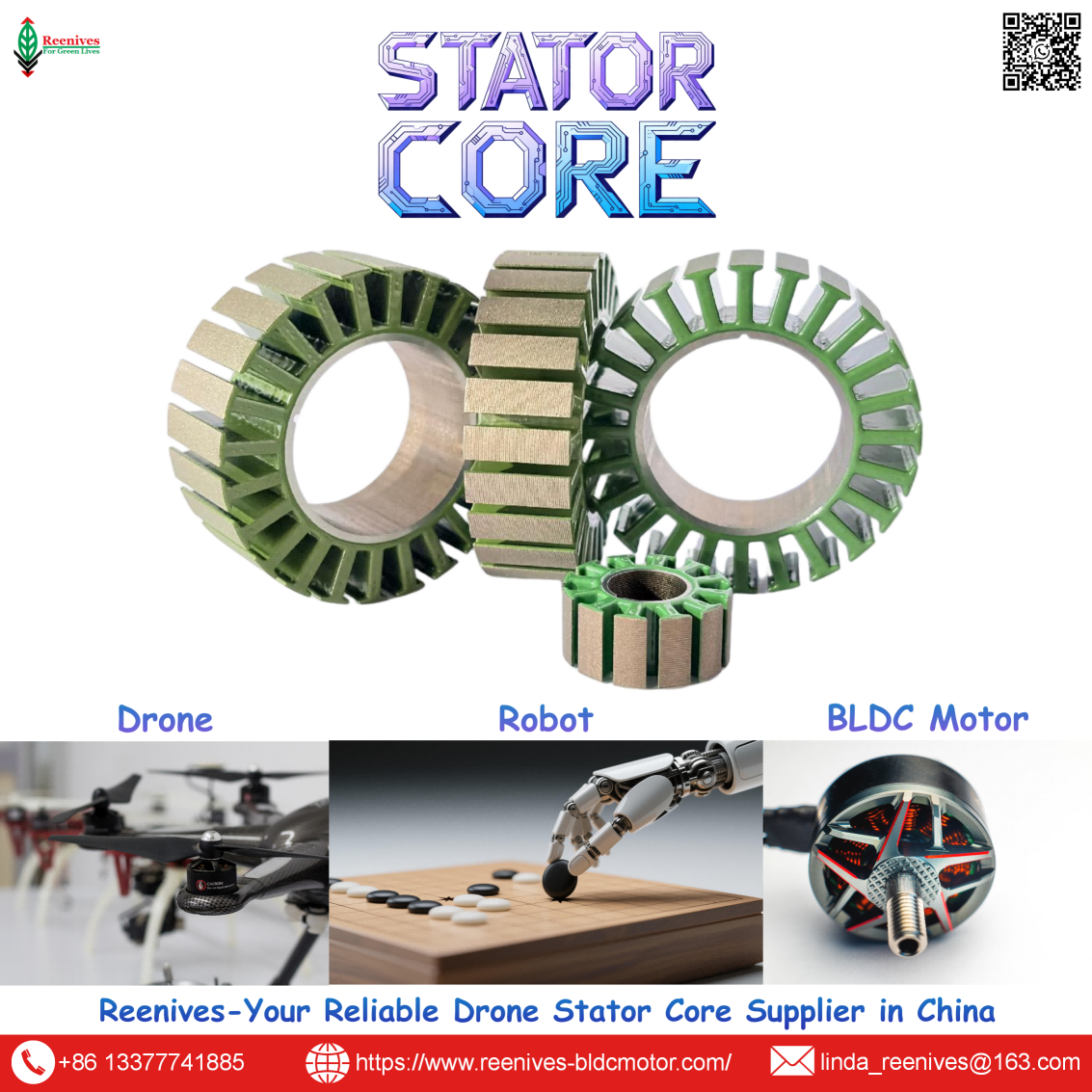
Reenives manufactures precision laminated stator and rotor cores engineered for high-fill winding: 0.20 mm low-loss non-grain-oriented silicon steel, interlocked or bonded stacking, C5/C6 epoxy coating for enamel protection, concentricity ≤0.02 mm, and slot geometry controlled to support consistent winding. Matched stator-rotor pairs, private mould development, and free samples are available for qualified drone and BLDC motor programs.
WhatsApp: +86-13377741885
Email: linda_reenives@163.com
Official website: www.reenives-bldcmotor.com
Dongguan Runlu Motor Technology Co., Ltd.
Reenives — Drone Motor One-Stop Solution Supplier
Reenives is a professional drone stator core manufacturer, founded in 2022. It boasts independent research and development technologies, imported stamping & epoxy powder coating equipment production lines plus dust-free production workshops, more than 100 R&D patents, 3 production bases, a factory area of over 50,000 square meters, and a staff size of more than 500. From production to sales, we support bulk purchasing, private mould development, and sample making, and can provide tailor-made perfect solutions for your production and usage scenarios. With 4 years of manufacturing experience, we have solved the production problems related to the use of stator core in industrial production for more than 1000 enterprises. We can ship globally (with complete export qualifications). Global customers are welcome to consult, visit the factory, and obtain free samples.
12N14P slot geometry0.20 mm / 0.35 mm NO silicon steelC5 / C6 epoxy coatingConcentricity ≤ 0.02 mmWinding-compatible slot toleranceMatched stator + rotor pairsGlobal export qualifications
How to Choose Suitable Motor Magnet for Drone?
Related Article


