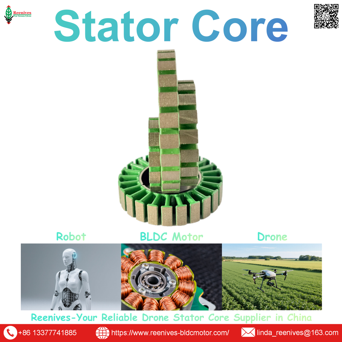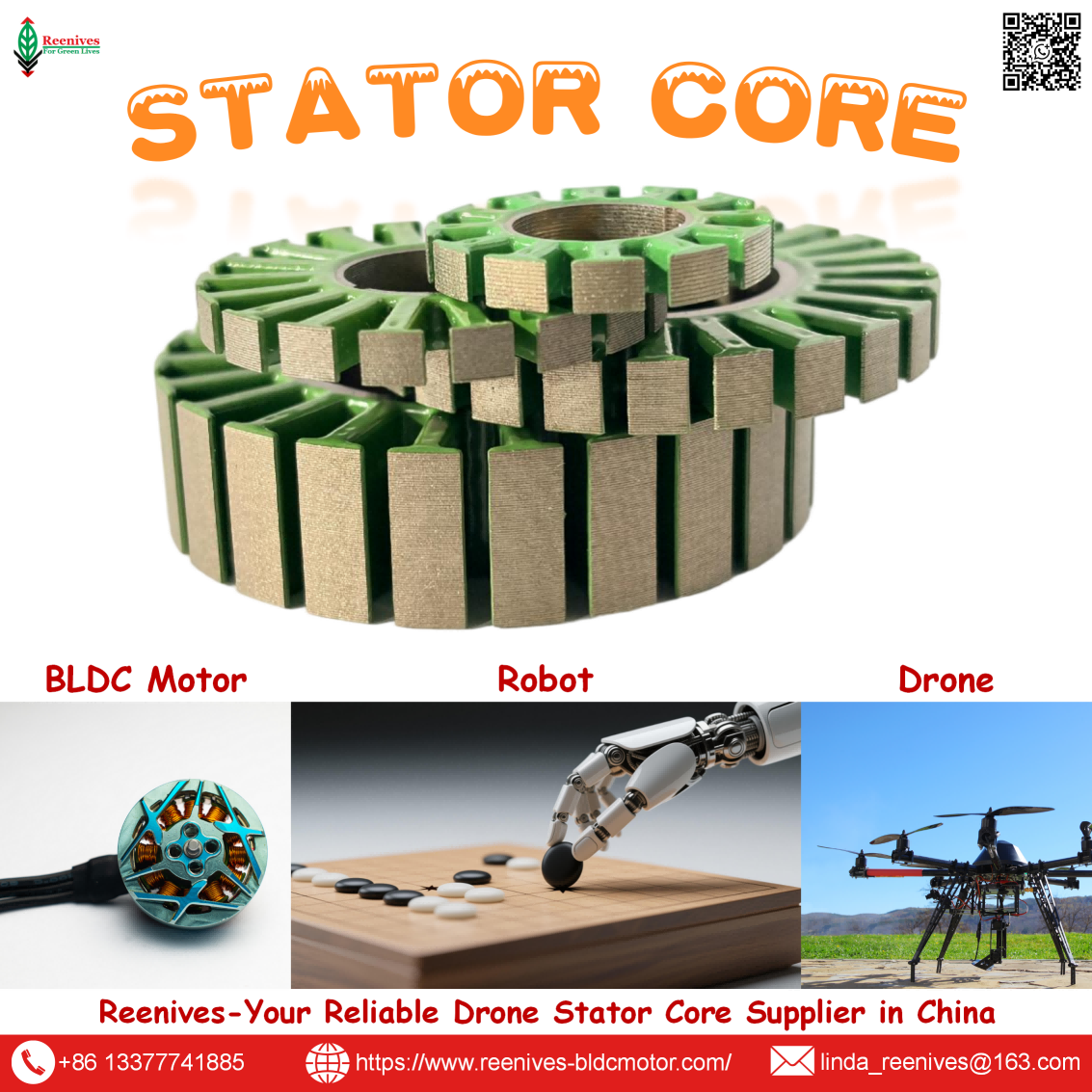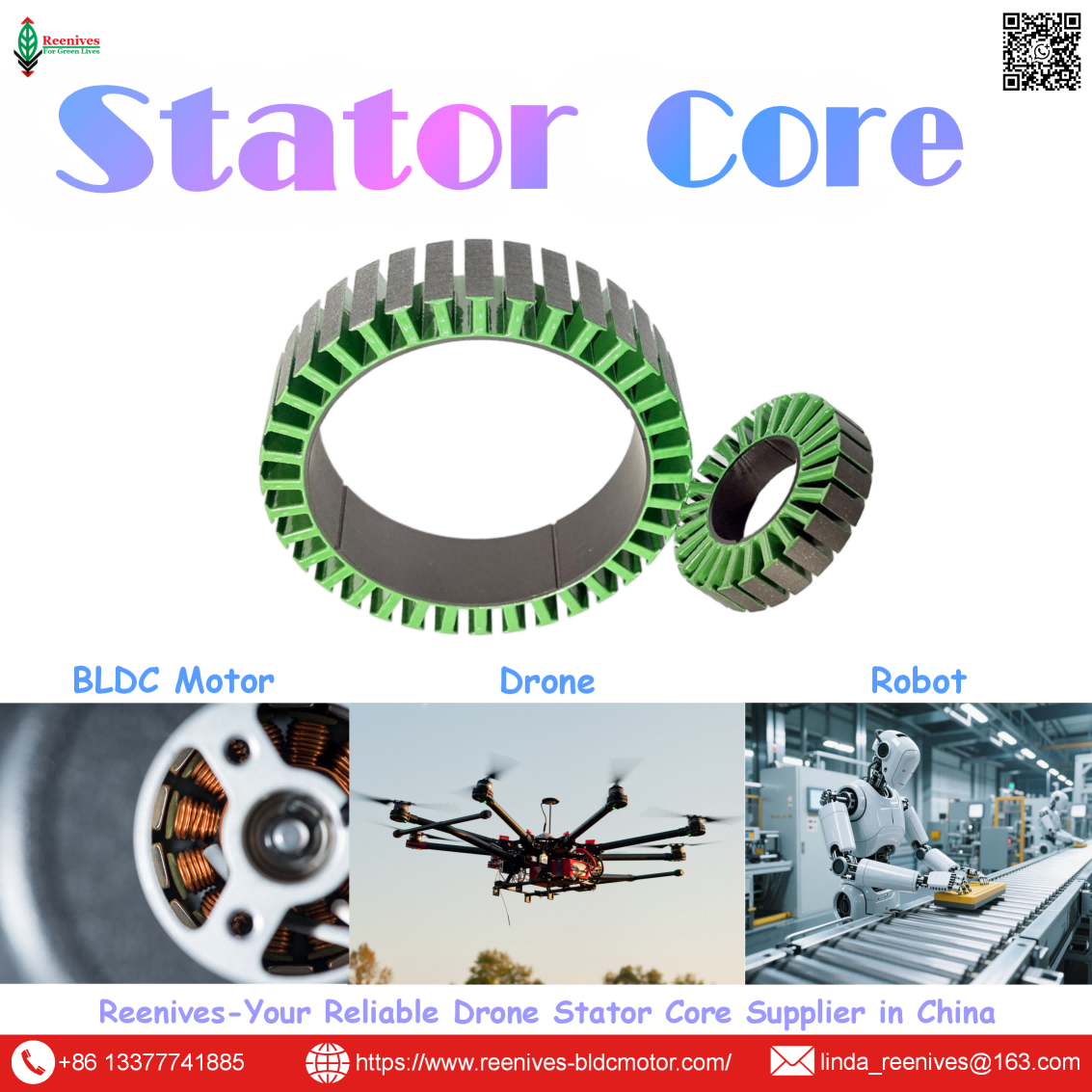
What is Radial Flux Motor?

What is a Radial Flux Motor? Flux Path, Slot-Pole Design, Stator Core Parameters, and Why It Dominates Drone Propulsion
More than 90% of the brushless motors flying on multirotors today are radial flux machines — and most buyers cannot explain why. The datasheet lists KV, stator size, and weight. It does not list the one structural property that makes the topology so dominant: in a radial flux motor, the magnetic attraction between the rotor and the stator cancels itself out symmetrically around the cylindrical air gap. That single fact means the rotor is reliably located without extra structure, torque can be doubled by lengthening the stator stack with a single tooling change, and the lamination supply chain that feeds the industry is mature and multi-sourced. Axial flux motors can beat radial flux on torque density and axial length, but they pay for it with dual air gaps, near-ton magnetic attraction during assembly, and a scalability ceiling that radial flux simply does not have.
This guide answers What is a radial flux motor? at the level a propulsion engineer or procurement lead needs: the flux-path definition and why it matters, the topology and slot-pole classifications that define drone motors, the published stator core parameters that determine whether the motor meets its thrust table, the mission profiles where radial flux is the correct choice, and a five-step selection workflow. Every published value in this article is expressed as a number plus a test standard plus a measurement location, so it can be audited on the finished part rather than taken from a mill certificate.
In this guide — jump to the section your project needs:
- What Is a Radial Flux Motor? The Flux-Path Definition and Why It Matters
- Radial Flux Motor Classification: Outrunner vs Inrunner, Slotted vs Slotless, 12N14P and Slot-Pole Families
- Published Stator Core Parameters: Core Loss, B50, Stacking Factor, Concentricity, Tolerance, Burr, Coating, Slot-Pole
- Application Profiles: Which Radial Flux Configuration Binds Which Drone Mission
- A 5-Step Radial Flux Motor Selection Workflow
- FAQ: Definition, 12N14P, Core Loss, B50, Stacking Factor, Burr, Concentricity, Coating, and Why Radial Flux Dominates
- Summary: Radial Flux Is the Default for a Structural Reason
What Is a Radial Flux Motor? The Flux-Path Definition and Why It Matters
A radial flux motor is a machine in which the magnetic flux between the stator and the rotor crosses the air gap perpendicular to the rotation axis — radially outward or inward — through a cylindrical gap between two coaxial cylinders. The stator is a slotted cylinder carrying the windings; the rotor is a coaxial cylinder carrying the permanent magnets, sitting either outside the stator (outrunner) or inside it (inrunner). Published descriptions define radial flux as a construction in which the magnetic field lines cross the air gap radially, and the stator and rotor are concentric cylinders — the conventional cylindrical layout.
That geometry has three structural consequences that explain why the topology dominates drone propulsion.
First, the magnetic attraction self-cancels. Because the air gap is a full cylinder, the magnetic pull on the rotor is balanced around the entire circumference. The rotor does not need a second air gap, a second rotor, or a stiff balancing structure to stay centred. Published engineering analysis of axial flux explicitly contrasts this: axial flux needs two rotors or two stators to cancel the attraction, which introduces a second air gap and roughly doubles the magnetic reluctance of the circuit.
Second, torque scales with a single parameter. The torque a radial flux motor produces is proportional to the cylindrical air-gap area, which grows with diameter × stack length. To double torque, you double the stack length — essentially a single-parameter change in design and tooling. Published scalability analysis uses exactly this comparison: doubling torque in radial flux is straightforward, while in axial flux it requires increasing diameter, which demands a more complete tooling change.
Third, the supply chain is mature and multi-sourced. Radial flux stator cores are produced by high-speed progressive stamping of non-oriented electrical steel — a process with a deep, competitive supplier base. Published comparisons note that radial flux motors remain dominant because of scalability and lower production costs, while axial flux serves compact, specialized applications at a 20–30% mass-production cost premium.
Procurement translation: “radial flux” is a structural description, not a quality tier. Two radial flux motors can share KV and stator dimensions and still differ in thermal margin, vibration, and field life — because the stator core behind them differs in lamination grade, stacking factor, burr control, and concentricity. The specification must name the topology and the stator core parameter set. A supplier who quotes “radial flux, 2207, 1750KV” has named the geometry and the envelope; they have not named the part that decides whether the motor holds its thrust curve.
Radial Flux Motor Classification: Outrunner vs Inrunner, Slotted vs Slotless, 12N14P and Slot-Pole Families
Rotor topology: outrunner versus inrunner
| Topology | Construction | Torque / Speed Character | Drone Role |
|---|---|---|---|
| Outrunner | Rotor bell with magnets spins around the outside of the stator | Larger torque radius; higher torque at lower RPM; direct propeller mounting | Dominant for multirotor, FPV, cinematic, and heavy-lift propulsion |
| Inrunner | Rotor spins inside the stator | Lower rotor inertia; faster dynamic response; higher speed ceiling | EDF and ducted-fan units, gimbal axes, high-speed propulsion |
Source: Published radial flux topology comparison (outrunner external rotor, inrunner internal rotor; torque-radius and inertia differences).
The outrunner dominates drone propulsion because a multirotor propeller needs relatively high torque at moderate RPM, and the outrunner’s larger torque radius delivers it without a gearbox. The inrunner’s lower inertia and higher speed ceiling suit ducted-fan and gimbal applications where rapid response matters more than raw torque. The distinction is structural: it changes the bearing arrangement, the air-gap location, and the thermal path, and it cannot be inferred from the KV rating.
Slot geometry: slotted versus slotless
| Geometry | Construction | Cogging | Torque Density | Drone Fit |
|---|---|---|---|---|
| Slotted | Teeth with slots; windings inserted into the slots | Present; suppressed by slot-pole choice and skew | Highest | Mainstream drone and FPV propulsion — the default |
| Slotless | No teeth; windings placed in the air gap | Essentially eliminated | Lower — larger effective air gap | High-speed, low-cogging applications; higher cost because more coil turns are needed |
Slot-pole families: 12N14P and the alternatives
The slot-pole combination defines the winding factor and the cogging profile, and it is fixed at the stator core design stage. 12N14P is the drone workhorse: 12 slots and 14 poles give slots per pole per phase of q = 12 ÷ (14 × 3) ≈ 0.286, a fractional-slot concentrated winding with a fundamental winding factor of approximately 0.933 and very low cogging torque. The slight asymmetry between slot and pole count means the magnets never align with all teeth simultaneously, which is why cogging is suppressed.
| Configuration | Slots | Poles | Winding Factor | Character | Typical Drone Fit |
|---|---|---|---|---|---|
| 12N14P | 12 | 14 | ≈0.933 | Very low cogging; short end turns | FPV, cinematic, multirotor — the default |
| 9N12P | 9 | 12 | — | Lighter; lower pole count reduces iron loss at high speed, slightly higher torque ripple | Small outrunners and lightweight high-speed builds |
| 18N24P | 18 | 24 | — | Higher slot count; different torque-ripple profile | Larger outrunners and industrial UAV platforms |
| 24N28P | 24 | 28 | — | High slot count; smooth torque character | Heavy-lift, logistics, and eVTOL propulsion |
Source: Published BLDC winding calculator (12N14P winding factor 0.933; 9N12P lower pole count reduces iron losses at the expense of slightly higher torque ripple); Reenives slot-pole configuration record.
The fixed-axis trap: the slot-pole combination cannot be changed by winding or assembly. A 12-slot stator cannot be rewound into a 9-slot stator, and a 14-pole rotor cannot become a 12-pole rotor. This is why the slot-pole parameter belongs in the stator core specification and must be confirmed before tooling is ordered — an error here requires a new die set, not a process adjustment.
Published Stator Core Parameters: Core Loss, B50, Stacking Factor, Concentricity, Tolerance, Burr, Coating, Slot-Pole
A radial flux motor’s performance is bounded by its stator core. The topology determines the structure; the core determines whether the structure delivers its rated thrust or quietly derates. The published parameter set below is expressed as value, standard, and measurement location, so it can be audited on the finished part.
| Parameter | Reenives Published Value | Test Standard / Method | Motor-Level Effect |
|---|---|---|---|
| Core loss | ≤9.5 W/kg @ 1.0 T / 400 Hz | IEC 60404-2 Epstein frame on the finished stack | Iron heat and the continuous torque ceiling |
| Lamination thickness | 0.20 mm non-oriented silicon steel | Micrometer, batch sampling | Eddy-current loss scaling with t² |
| B50 flux density | 1.65–1.72 T | IEC 60404-2 magnetic property test | Torque per unit magnet field; saturation onset |
| Stacking factor | ≥97% (epoxy bonded) | Weight / dimension method | Effective flux density of the finished stack |
| Concentricity | ≤0.02 mm | Vision measurement on finished core | Air-gap uniformity, vibration, bearing load |
| Critical tolerance | ±0.05 mm | Metrology on finished core | Fixture seating consistency; air-gap shift |
| Burr height | <0.03 mm | Optical comparator edge scan | Prevents coating piercing and interlaminar short |
| Coating class | C5 epoxy (C6 for harsh environments) | Visual + dielectric check | Interlaminar insulation across service life |
| Dielectric strength | >1400 V | ASTM D149 | Withstand voltage before breakdown |
| Operating temperature | −40°C to 180°C (200°C peak) | Coating temperature class | Insulation survival at continuous duty |
| Slot-pole | 12N14P (with 9N12P, 18N24P, 24N28P) | Dimensional inspection | Winding factor ≈0.933; cogging profile |
Sources: Reenives radial flux drone stator core specification (core loss, lamination thickness, B50, stacking factor, concentricity, tolerance, burr, coating, dielectric strength, temperature range, slot-pole); IEC 60404-2 Epstein-frame method; ASTM D149 dielectric strength standard.
Core loss: the thermal ceiling
Core loss has two components: hysteresis loss, proportional to frequency and the material’s coercivity, and eddy-current loss, proportional to the square of both lamination thickness and frequency. At drone electrical frequencies — hundreds of hertz to over 1 kHz — the eddy-current term dominates, and it scales with the square of thickness. Published comparison data places a 0.35 mm grade at roughly 28–35 W/kg at 1.0 T / 400 Hz, a generic 0.20 mm grade at roughly 10–14 W/kg, and the Reenives 0.20 mm grade at ≤9.5 W/kg measured per IEC 60404-2. The 0.35 → 0.20 mm switch reduces eddy-current loss by approximately 67% at the same flux density, which becomes lower winding temperature and longer continuous torque headroom.
B50 and stacking factor: the flux-density pair
B50 is the flux density measured at a magnetizing field of 5,000 A/m, and it defines the torque-per-amp ceiling at the material level. A core at the low end of the 1.65–1.72 T band saturates earlier, so the motor draws more current for the same torque and runs hotter. Stacking factor is the ratio of actual magnetic steel volume to the total stack envelope, measured by the weight/dimension method. Moving from a 96% to a 98% stacking factor raises effective flux density by roughly 6% without any change to the mill certificate — which is why a loose stack wastes the grade the buyer paid for.
Concentricity, tolerance, and burr: the manufacturing controls
Concentricity ≤0.02 mm is the deviation of the stator bore centre from the outer diameter centre. It defines half the air gap: a 0.02 mm error on each side is a meaningful fraction of a 0.10–0.12 mm FPV air gap. Critical tolerance ±0.05 mm governs how consistently the stator seats in the winding fixture and how closely the bore matches the nominal design. Burr height <0.03 mm is the raised edge left by stamping; a burr can pierce the interlamination coating of the adjacent sheet during stacking and create a local short that becomes a hot spot. All three must be measured on the finished core, not inferred from the mill certificate.
Coating: the survival barrier
C5 epoxy powder coating at >1400 V per ASTM D149, across −40°C to 180°C with a 200°C short-term peak, is the interlamination electrical barrier. It is not a finish. During winding, tension and tool contact can abrade or pierce it; during operation, thermal cycling and vibration stress it further. A uniform, pinhole-free layer survives both; a thin or voided layer can pass the initial electrical test and break down after hours of flight. C6 is available where harsher chemical or thermal duty applies.
The audit rule: a parameter without a test standard and a measurement location is a description, not a specification. “Core loss ≤9.5 W/kg” is a description. “Core loss ≤9.5 W/kg at 1.0 T / 400 Hz, measured per IEC 60404-2 on the finished stack” is a specification. Apply the same test to concentricity (“≤0.02 mm, vision, finished core”), burr (“<0.03 mm, optical comparator”), and dielectric strength (“>1400 V, ASTM D149”). A quote that omits the standard and the location leaves the interpretation to the supplier.
Application Profiles: Which Radial Flux Configuration Binds Which Drone Mission
| Mission Class | Radial Flux Configuration | Binding Parameter | Specification to Write |
|---|---|---|---|
| FPV racing / freestyle | Outrunner, slotted, 12N14P or 9N12P | Core loss at high electrical frequency | 0.20 mm at ≤9.5 W/kg @ 1.0 T / 400 Hz; 12N14P winding factor ≈0.933 |
| Cinematic / inspection | Outrunner, slotted, 12N14P | Concentricity and cogging profile | Concentricity ≤0.02 mm; 12N14P low cogging; tolerance ±0.05 mm |
| Agricultural spraying | Outrunner, slotted, 18N24P | Coating dielectric strength and temperature range | C5 epoxy >1400 V per ASTM D149; −40°C to 180°C; burr <0.03 mm |
| Heavy-lift / logistics | Outrunner, slotted, 18N24P or 24N28P | Stacking factor and B50 | Stacking factor ≥97%; B50 1.65–1.72 T; core loss ≤9.5 W/kg |
| EDF / gimbal | Inrunner | Rotor inertia and speed ceiling | Inrunner topology; concentricity ≤0.02 mm; balancing grade on the rotor |
The pattern is that the binding parameter tracks the mission’s dominant failure mechanism. FPV racing binds on core loss because high electrical frequency converts iron loss into heat that sags the thrust curve. Cinematic and inspection platforms bind on concentricity and cogging because vibration reaches the payload before it reaches the pilot. Agricultural platforms bind on coating and temperature range because the duty cycle is long, wet, and thermal. Heavy-lift binds on stacking factor and B50 because continuous torque depends on the flux density the finished stack actually delivers. Inrunner applications bind on inertia and speed ceiling because the mission is response, not raw torque.
A 5-Step Radial Flux Motor Selection Workflow
- Fix the application class and the propeller before the motor. State the all-up weight, propeller diameter, voltage platform, and continuous duty cycle. The propeller determines the torque and RPM the motor must deliver; the motor exists to serve it. A 5-inch FPV on 6S and a 30-inch heavy-lift on 14S sit in different application classes, and the KV band follows from the class: high KV (2000–4000+) for small propellers, mid KV (1000–2000) for 5-inch freestyle, low KV (90–1000) for large propellers and heavy-lift.
- Choose the rotor topology and slot geometry from the structural requirement. For multirotor propulsion, the outrunner with a slotted stator is the default because the larger torque radius delivers the required torque without a gearbox. For EDF, ducted fan, or gimbal applications, the inrunner’s lower inertia and higher speed ceiling are the reason to select it. Slotless geometry is reserved for high-speed, low-cogging applications where the reduced torque density is acceptable.
- Confirm the slot-pole combination before tooling is ordered. Specify 12N14P for the drone workhorse — q ≈ 0.286, winding factor ≈ 0.933, very low cogging — or 9N12P for lightweight high-speed builds, 18N24P or 24N28P for larger high-torque platforms. Because the slot-pole pair is fixed at the core design stage, an error here requires a new die set rather than a process adjustment.
- Specify the stator core with value, standard, and location for every parameter. Write 0.20 mm non-oriented silicon steel, core loss ≤9.5 W/kg at 1.0 T / 400 Hz per IEC 60404-2 on the finished stack, B50 1.65–1.72 T, stacking factor ≥97%, concentricity ≤0.02 mm by vision, critical tolerance ±0.05 mm, burr height <0.03 mm by optical comparator, and C5 epoxy coating at >1400 V per ASTM D149 across −40°C to 180°C. A quote that omits the standard and the location leaves the interpretation to the supplier.
- Run a trial sample and audit the evidence before volume commitment. Send the motor design intent to the core supplier and request a finished-stack core-loss report, a stacking-factor measurement, a concentricity record, a burr measurement, and a rejected unit from their inspection process. Confirm that the electrical frequency at the intended operating RPM (RPM × pole pairs ÷ 60) falls where the specified grade delivers its published loss — for a 14-pole motor at 15,000 RPM that is 1,750 Hz, well into the range where the 0.20 mm grade is the baseline rather than an upgrade.
FAQ: Definition, 12N14P, Core Loss, B50, Stacking Factor, Burr, Concentricity, Coating, and Why Radial Flux Dominates
What is a radial flux motor, in one sentence?
A radial flux motor is a permanent-magnet or wound-field machine in which the magnetic flux between the stator and rotor crosses the air gap perpendicular to the rotation axis — radially outward or inward — through a cylindrical gap between two coaxial cylinders. The stator is a slotted cylinder carrying the windings, and the rotor is a coaxial cylinder carrying the permanent magnets, sitting either outside the stator (outrunner) or inside it (inrunner). Published descriptions define radial flux as the construction in which field lines cross the air gap radially — the conventional cylindrical layout used in the vast majority of drone propulsion motors.
Source: Published radial flux definition (flux perpendicular to the axis, cylindrical air gap, concentric stator and rotor).
What is the 12N14P slot-pole combination, and what winding factor does it achieve?
12N14P means 12 stator slots and 14 rotor poles. The slots per pole per phase calculate to q = 12 ÷ (14 × 3) ≈ 0.286, making it a fractional-slot concentrated winding. For a typical single-layer concentrated winding the fundamental winding factor reaches approximately 0.933, and the slight slot-pole asymmetry means the magnets never align with all teeth simultaneously, which keeps cogging torque very low. That combination — high winding factor, low cogging, short end turns, and a compact outrunner package — is why 12N14P is the default for drone and multirotor propulsion.
Source: Published BLDC winding calculator (12N14P winding factor 0.933; concentrated fractional-slot winding; low cogging from slot-pole asymmetry).
What core loss should a radial flux drone stator core specify, and at what test point?
Reenives publishes ≤9.5 W/kg at 1.0 T / 400 Hz for its 0.20 mm drone grade, measured by the Epstein frame per IEC 60404-2. The test point and standard matter as much as the number: IEC 60404-2 requires a sinusoidal polarization waveform, a measurement temperature of 23°C ±5°C, and no external stress on the specimen. For comparison, a generic 0.20 mm grade runs at roughly 10–14 W/kg at the same test point and a 0.35 mm grade at roughly 28–35 W/kg. Because eddy-current loss scales with the square of lamination thickness, the thickness and grade must be specified together with the finished-stack measurement.
Source: Reenives 0.20 mm stator core specification (≤9.5 W/kg @ 1.0 T / 400 Hz, IEC 60404-2); published lamination comparison (generic 0.20 mm 10–14 W/kg; 0.35 mm 28–35 W/kg).
What B50 flux density and stacking factor should a radial flux drone stator core hold?
Reenives publishes B50 of 1.65–1.72 T and a stacking factor of ≥97% (epoxy bonded) for its 0.20 mm radial flux drone stator cores. B50 is the flux density measured at a magnetizing field of 5,000 A/m and defines the torque-per-amp ceiling at the material level: a core at the low end of the band saturates earlier, so the motor draws more current for the same torque. Stacking factor is the ratio of actual magnetic steel volume to the total stack envelope, measured by the weight/dimension method; moving from 96% to 98% raises effective flux density by roughly 6% without any change to the mill certificate.
Source: Reenives 0.20 mm stator core specification (B50 1.65–1.72 T; stacking factor ≥97% by weight/dimension); published stacking factor performance analysis.
What burr height and concentricity should a radial flux drone stator core hold?
Reenives specifies burr height <0.03 mm by optical comparator and concentricity ≤0.02 mm by vision measurement on the finished core, with critical tolerance ±0.05 mm. Burr is the raised metal edge left by stamping; a burr can pierce the interlamination coating of the adjacent sheet during stacking and create a local short that becomes a hot spot. Concentricity is the deviation of the stator bore centre from the outer diameter centre, and it defines half the air gap — a 0.02 mm error on each side is a meaningful fraction of a 0.10–0.12 mm FPV air gap. Both parameters must be measured on the finished part, not inferred from a mill certificate.
Source: Reenives stator core specification (burr <0.03 mm, optical comparator; concentricity ≤0.02 mm, vision; tolerance ±0.05 mm); published air-gap and interlaminar short analysis.
What coating and dielectric strength should a radial flux drone stator core carry?
Reenives specifies C5 epoxy powder coating with dielectric strength >1400 V per ASTM D149, across an operating range of −40°C to 180°C with a 200°C short-term peak; C6 is available for harsher environments. The coating is the interlamination electrical barrier, not a finish. During winding, tension and tool contact can abrade or pierce it; during operation, thermal cycling and vibration stress it further. A uniform, pinhole-free layer survives both, while a thin or voided layer can pass the initial electrical test and break down after hours of flight.
Source: Reenives C5/C6 epoxy coating specification (>1400 V per ASTM D149; −40°C to 180°C operating, 200°C peak); ASTM D149 standard.
Why does radial flux dominate drone propulsion if axial flux has higher torque density?
Because the radial flux structure solves the magnetic attraction problem for free and scales with a single tooling parameter. In a radial flux motor the attraction between rotor and stator cancels symmetrically across the cylindrical surface, so the rotor is reliably located without extra structure. Doubling torque is done by lengthening the stator and rotor, which is essentially a single-parameter change in design and tooling. The lamination supply chain is also mature and multi-sourced. Axial flux offers higher torque density in a short axial package, but requires dual air gaps, near-ton magnetic attraction during assembly, ±tens-of-microns gap uniformity, and a diameter change — not a length change — to scale torque. For volume drone production, radial flux remains the lower-risk, lower-cost topology.
Source: Published axial vs radial structural comparison (self-cancelling attraction, dual gap, scalability by lengthening vs diameter); published radial flux dominance due to scalability and lower production costs.
Summary: Radial Flux Is the Default for a Structural Reason
A radial flux motor routes magnetic flux perpendicular to the shaft across a cylindrical air gap. That geometry delivers three properties that explain why it powers the vast majority of drones: the magnetic attraction self-cancels around the full circumference, so the rotor stays centred without extra structure; torque scales by lengthening the stator stack, a single-parameter tooling change; and the progressive-stamped lamination supply chain is mature and multi-sourced. Axial flux can beat radial flux on torque density and axial length, but it pays with dual air gaps, near-ton assembly attraction, ±tens-of-microns gap uniformity, and a diameter-change scaling ceiling.
The published stator core parameter set for a radial flux drone motor is concrete: 0.20 mm non-oriented silicon steel, core loss ≤9.5 W/kg at 1.0 T / 400 Hz per IEC 60404-2 on the finished stack, B50 1.65–1.72 T, stacking factor ≥97%, concentricity ≤0.02 mm, critical tolerance ±0.05 mm, burr height <0.03 mm, and C5 epoxy coating at >1400 V per ASTM D149 across −40°C to 180°C, in 12N14P (winding factor ≈0.933, very low cogging) with 9N12P, 18N24P, and 24N28P alternatives. Each value is expressed as number plus standard plus location, so it can be audited on the finished part.
The procurement takeaway is that the topology label is the beginning of the specification, not the end. A supplier who quotes “radial flux, 2207, 1750KV” has named the geometry and the envelope; a supplier who can also restate the core-loss figure with its standard, the B50 and stacking factor with their methods, the concentricity and burr limits with their instruments, and the coating dielectric strength with its test standard is describing the part that decides whether the motor holds its thrust curve. That is the difference between a topology quote and a motor specification.
Specifying radial flux stator cores for a drone motor programme?
Reenives publishes the complete radial flux stator core specification: 0.20 mm non-oriented silicon steel, core loss ≤9.5 W/kg at 1.0 T / 400 Hz per IEC 60404-2, B50 1.65–1.72 T, stacking factor ≥97%, concentricity ≤0.02 mm, critical tolerance ±0.05 mm, burr height <0.03 mm, and C5 epoxy coating at >1400 V per ASTM D149, in 9N12P, 12N14P, 18N24P, and 24N28P configurations. Finished-stack reports, matched stator-rotor pairs, private mould development, and free samples are available for qualified engineering evaluations.
WhatsApp: +86-13377741885
Email: linda_reenives@163.com
Official website: www.reenives-bldcmotor.com
Dongguan Runlu Motor Technology Co., Ltd.
Reenives — Drone Motor One-Stop Solution Supplier
Reenives is a professional drone stator core manufacturer, founded in 2022. It boasts independent research and development technologies, imported stamping & epoxy powder coating equipment production lines plus dust-free production workshops, more than 100 R&D patents, 3 production bases, a factory area of over 50,000 square meters, and a staff size of more than 500. From production to sales, we support bulk purchasing, private mould development, and sample making, and can provide tailor-made perfect solutions for your production and usage scenarios. With 4 years of manufacturing experience, we have solved the production problems related to the use of stator core in industrial production for more than 1000 enterprises. We can ship globally (with complete export qualifications). Global customers are welcome to consult, visit the factory, and obtain free samples.
0.20 mm silicon steelCore loss ≤9.5 W/kg @ 1.0 T / 400 HzB50 1.65–1.72 TStacking factor ≥97%Concentricity ≤0.02 mmBurr <0.03 mmC5 epoxy >1400 V9N12P · 12N14P · 18N24P · 24N28PGlobal export qualifications
Processing Flow of Axial Flux Electric Motor
Axial Flux Motor VS Radial Flux Motor
Related Article