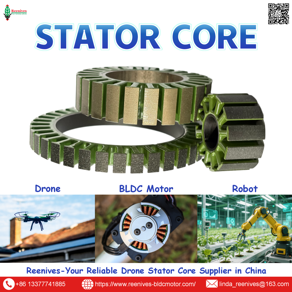
Drone Motor Stator Lamination Drawing Supplier

Stator Lamination Drawing — Engineering Drawings for Drone & BLDC Motor Lamination Stators | Reenives Stator Core Supplier
⚠️ Is your stator lamination drawing incomplete, ambiguous, or missing critical tolerances — causing tooling delays, wrong parts, or motor performance issues? Poorly defined drawings lead to die rework, scrap, and extended lead times. Missing slot geometry, unclear burr limits, or undefined coating specs can derail your drone motor project before it reaches production.
✅ Reenives supports engineers with engineering-grade stator lamination drawing review and DFM feedback. Send us your CAD or concept, and our team will review slot/pole geometry, tolerances, material grade, stack length, and coating requirements — then return a tooling-ready drawing for approval. As a reliable drone motor stator lamination drawing supplier, we help 1000+ enterprises move from concept to production faster.
📋 Table of Contents
What Is a Stator Lamination Drawing?
A stator lamination drawing is a 2D engineering document that defines the exact geometry, dimensions, tolerances, material, and coating requirements for a single lamination layer of a motor stator core. It is the master reference used for die design, stamping, stacking, and quality inspection.
In drone motor development, the stator lamination drawing bridges electrical design and manufacturing. A complete drawing must define:
- Outer diameter (OD) & inner diameter (ID)
- Slot count, slot shape & tooth width
- Yoke width, slot depth & root radius
- Material grade & lamination thickness
- Insulation coating type & thickness
- Interlock / bonding / welding features
- Datum, tolerances & burr limits
For drone BLDC motors, the drawing directly determines whether the stator achieves the required torque, efficiency, cogging torque, and thermal performance. An incomplete drawing is the most common cause of tooling delays and production scrap.

Engineering-grade stator lamination drawing — developed and reviewed by Reenives for tooling-ready drone motor production.
Types of Stator Lamination Drawings
Stator lamination drawings vary in detail and purpose depending on project stage and manufacturing method. Reenives works with and prepares the following drawing types:
- Concept / Layout Drawings — Early-stage drawings defining slot count, pole count, OD/ID, and stack length. Used for feasibility studies and motor sizing.
- Detailed Manufacturing Drawings — Full 2D drawings with all critical dimensions, tolerances, datum references, and GD&T callouts for die design.
- Segmented Lamination Drawings — Drawings for individual tooth segments, used when windings are applied before core assembly.
- Interlocked Lamination Drawings — Drawings including interlock dimple geometry, depth, and position for mechanical stacking.
- Bonded Lamination Drawings — Drawings specifying adhesive bonding zones and curing requirements instead of interlocking.
- Epoxy-Coated Lamination Drawings — Drawings defining coating thickness, coverage, and masking areas for insulation.
- Stack Assembly Drawings — Drawings defining stack length, end plate geometry, and assembly method for the completed stator core.
- Custom Lamination Drawings — Private mould development drawings for unique slot profiles, tooth shapes, and mounting features.
Whether you need a concept layout or a fully detailed manufacturing drawing, Reenives can support your engineering team.
Critical Drawing Dimensions & Data
Below are the key dimensions and specifications that should appear on a complete stator lamination drawing for drone and BLDC motors.
| Drawing Element | Typical Range / Value | Notes |
|---|---|---|
| Lamination Material | Silicon steel (e.g., 35WW250, 50WW470) | Specify grade on drawing |
| Lamination Thickness | 0.20 mm – 0.50 mm | Nominal ±0.01 mm typical |
| Outer Diameter (OD) | 20 mm – 200 mm | ±0.05 mm (critical) |
| Inner Diameter (ID) | 10 mm – 180 mm | ±0.05 mm (critical) |
| Stack Length | 5 mm – 80 mm | ±0.10 mm typical |
| Slot Number | 6, 9, 12, 18, 24, etc. | Must match pole count |
| Slot Width / Tooth Width | 1.0 mm – 15 mm | ±0.03 mm typical |
| Yoke Width | 1.5 mm – 20 mm | ±0.05 mm typical |
| Burr Height | ≤ 0.03 mm | Specify max on drawing |
| Insulation Coating | Epoxy powder coating | Specify thickness (e.g., 10–30 µm) |
| Interlock / Bonding | Dimple, dovetail, or adhesive | Define geometry & position |
| Datum Reference | ID or OD (typically ID) | Define per GD&T standard |
Data source: Reenives engineering drawing standards, based on drone motor production experience, 2024. Actual values may vary by design.
Applications of Stator Lamination Drawings
Stator lamination drawings are used across a wide range of drone and brushless motor development projects:
- FPV Racing Drone Motors — Drawings optimized for high RPM, lightweight lamination stacks with low cogging torque.
- Cinematic & Photography Drone Motors — Drawings for smooth, vibration-free stators to ensure stable aerial footage.
- Agricultural Spraying Drone Motors — Drawings specifying epoxy coating for corrosion resistance in harsh environments.
- Industrial Inspection Drone Motors — Drawings for high-torque stators with extended stack length and larger diameters.
- eVTOL & UAV Propulsion Motors — Custom drawings for high-power stator cores with unique slot/pole combinations.
- Robot Actuators — Drawings for low cogging torque stators with high pole counts for precise motion control.
- General BLDC Motors — Drawings for fans, pumps, power tools, and automotive actuators.

Reenives stator lamination drawings enable precise tooling and production for FPV, agricultural, cinematic, and industrial UAVs worldwide.
How to Prepare a Tooling-Ready Stator Lamination Drawing
To avoid tooling delays and production issues, your stator lamination drawing should include the following. Use this as a checklist when preparing drawings for your supplier:
- Define the Lamination Profile — Include OD, ID, slot count, slot shape, tooth width, yoke width, and root radius. Use a full-scale 2D view with all dimensions.
- Specify Material & Thickness — State the silicon steel grade (e.g., 35WW250) and nominal lamination thickness with tolerance.
- Set Critical Tolerances — Define tolerances for OD, ID, slot width, tooth width, and stack length. Use GD&T datum references where possible.
- Define Burr Height Limit — Specify maximum allowable burr height (typically ≤ 0.03 mm) to ensure clean stacking and reduce shorts.
- Specify Insulation Coating — State coating type (epoxy powder), thickness, and coverage requirements, including any masking areas.
- Define Stacking Method — Indicate whether laminations are interlocked, bonded, welded, or clamped. Include interlock geometry if applicable.
- Add Assembly & Mounting Features — Include mounting holes, keyways, end plate interfaces, and any shaft-related features.
- Request DFM Review — Send your drawing to Reenives for a design-for-manufacturing review. We will flag tooling risks, tolerance challenges, and cost drivers before die fabrication begins.
FAQ — Stator Lamination Drawing Parameters
Q1: What file formats do you accept for stator lamination drawings?
A: We accept 2D drawings in PDF, DWG, or DXF format, as well as 3D models in STEP or IGES format. For tooling design, a 2D drawing with complete dimensions and tolerances is required. If you only have a 3D model, our engineering team can generate a 2D drawing for your approval before die fabrication.
Source: Reenives engineering workflow, 2024.
Q2: What lamination thickness should be specified on the drawing for high-RPM drone motors?
A: For high-RPM drone motors (above 10,000 RPM), specify 0.20 mm or 0.25 mm silicon steel laminations on the drawing. Thinner laminations significantly reduce eddy current losses, which helps keep the motor cool and improves efficiency. For lower RPM applications, 0.35 mm or 0.50 mm can be more cost-effective.
Source: Reenives engineering team, based on motor design guidelines and material datasheets.
Q3: What critical tolerances should be included on a stator lamination drawing?
A: Critical tolerances typically include: inner diameter ±0.05 mm, outer diameter ±0.05 mm, slot width ±0.03 mm, tooth width ±0.03 mm, and stack length ±0.10 mm. Burr height should be limited to ≤ 0.03 mm. We recommend using GD&T datum references (typically the inner diameter) to ensure consistent measurement and inspection.
Source: Reenives quality control standards, 2024.
Q4: Why is burr height specified on a stator lamination drawing?
A: Burr height is critical because burrs create localized shorts between laminations, increasing eddy current losses and reducing motor efficiency. Excessive burrs also cause uneven stacking, leading to vibration and dimensional errors. We recommend specifying a maximum burr height of ≤ 0.03 mm, which our high-speed stamping process consistently achieves with optimized die clearance and maintenance.
Source: Reenives engineering team, based on motor design principles and stamping experience.
Q5: Do you offer DFM feedback on stator lamination drawings?
A: Yes. We provide design-for-manufacturing (DFM) feedback at no cost for qualified projects. Our engineering team reviews your drawing for tooling feasibility, tolerance challenges, material selection, and cost drivers. We flag any features that may increase die cost or risk production issues, and we propose alternatives where appropriate. This helps you avoid expensive rework and shorten your development cycle.
Source: Reenives custom development process.
Q6: Can you develop a stator lamination drawing from a concept or sample?
A: Absolutely. If you have a concept sketch, a physical sample, or performance requirements without a drawing, our engineering team can develop a complete stator lamination drawing for your review. We will define the slot/pole combination, material grade, thickness, tolerances, and coating specification based on your motor requirements. Drawing development typically takes 3–7 days, followed by tooling fabrication.
Source: Reenives custom development process.
Summary — Get Your Stator Lamination Drawing Reviewed Today
Ready to Move from Drawing to Production Faster?
A complete, tooling-ready stator lamination drawing is the foundation of a successful drone motor project. Reenives supports your engineering team with DFM review, tolerance optimization, and tooling-ready drawing preparation. As a reliable drone motor stator lamination drawing supplier, we help 1000+ enterprises shorten development cycles and reduce tooling risk.
📦 Bulk purchasing · 🔧 Private mould development · 🧪 Free samples
🌐 Official Website: www.reenives-bldcmotor.com
📧 Email: linda_reenives@163.com
Contact us now for a free drawing review and tailored solution for your production scenario.
Dongguan Runlu Motor Technology Co., Ltd.
Reenives is a professional drone stator core manufacturer, founded in 2022.
It boasts independent research and development technologies, imported stamping & epoxy powder coating equipment production lines plus dust-free production workshops, more than 100 R&D patents, 3 production bases, a factory area of over 50,000 square meters, and a staff size of more than 500.
From production to sales, we support bulk purchasing, private mould develop, and samples making, and can provide tailor-made perfect solutions for your production and usage scenarios. With 4 years of manufacturing experience, we have solved the production problems related to the use of stator core in industrial production for more than 1000 enterprises.
We can ship globally (with complete export qualifications). Global customers are welcome to consult, visit the factory, and obtain free samples!
Reenives Runlu Motor Stator Lamination Drawing
BLDC Motor Stator Lamination Supplier
Outrunner BLDC Motor Stator Laminations Supplier
Related Article