Reenives: Global Leading UAV FPV Drone Motor Stator Rotor One-Stop Solution Supplier

Stator Rotor: Why an FPV Drone Motor Sourced as Two Separate Parts Rarely Survives 20,000 RPM
The first sign is usually gyro noise the pilot cannot tune out. Then a bearing goes, and the motor bell starts to wobble. By the time the quad is on the bench, the diagnosis reads “bearing failure” or “crashed bell” — but the root cause was set at the purchase order. In an FPV outrunner, the stator rotor pair is not two parts bolted together; it is one magnetic circuit separated by an air gap measured in tenths of a millimetre. Source the stator from one vendor and the rotor from another, and that gap is toleranced by two process chains with no shared datum. At 20,000+ RPM, the mismatch does not stay theoretical. It becomes vibration, heat, and a bearing that dies early.
The published specifications make the problem concrete. Reenives lists a typical air gap of 0.2 mm – 1.0 mm for drone stator-rotor pairs, with ±0.05 mm tolerance on critical dimensions and a stacking factor of ≥95%. Production FPV motors often run tighter still: a published 2306 FPV motor specifies a 0.10–0.12 mm air gap, and another FPV motor listing cites a 0.1 mm ultra-small gap for reduced magnetic loss. At those dimensions, a 0.05 mm variation is not a tolerance detail — it is a measurable change in magnetic pull, vibration, and bearing load. Reenives' own engineering guidance states it directly: “even a 0.05 mm air gap variation can cause measurable vibration and power loss” in high-RPM drone motors.
This guide answers the Stator Rotor question at the level an FPV propulsion engineer or procurement lead needs: what the pair is as a magnetic circuit, the configurations that matter, the published parameters and the standards behind them, the mission profiles where the pair-level tolerance binds, and a five-step qualification workflow that turns “matched pair” from a brochure phrase into an auditable purchase requirement.

In this guide — jump to the section your project needs:
- What Is an FPV Stator Rotor Pair? The Magnetic Circuit, Not Two Parts
- Matched-Pair Configurations for FPV and UAV Motors: Outrunner, Inrunner, Segmented, IPM
- Published Parameters and Verification: Air Gap, Tolerance, Stacking Factor, Core Loss, Rotor Balance, Magnet Grade
- Application Profiles: Which Pair Parameter Binds Which FPV Mission
- A 5-Step Qualification Workflow for a Matched Stator Rotor Supplier
- FAQ: Air Gap, Tolerance, Core Loss, Rotor Balance, and Eccentricity
- Summary: Buy the Magnetic Circuit, Not Two Parts
What Is an FPV Stator Rotor Pair? The Magnetic Circuit, Not Two Parts
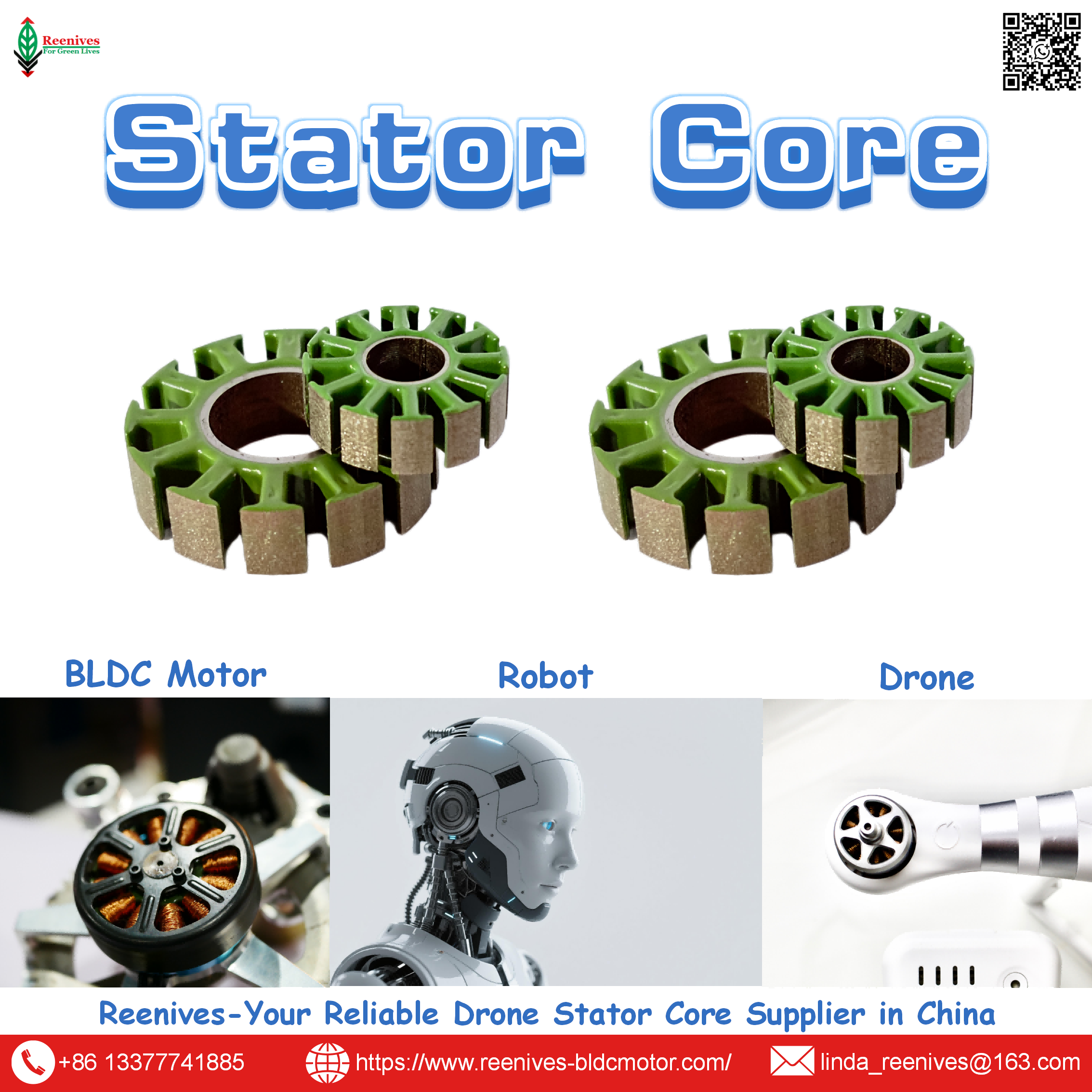
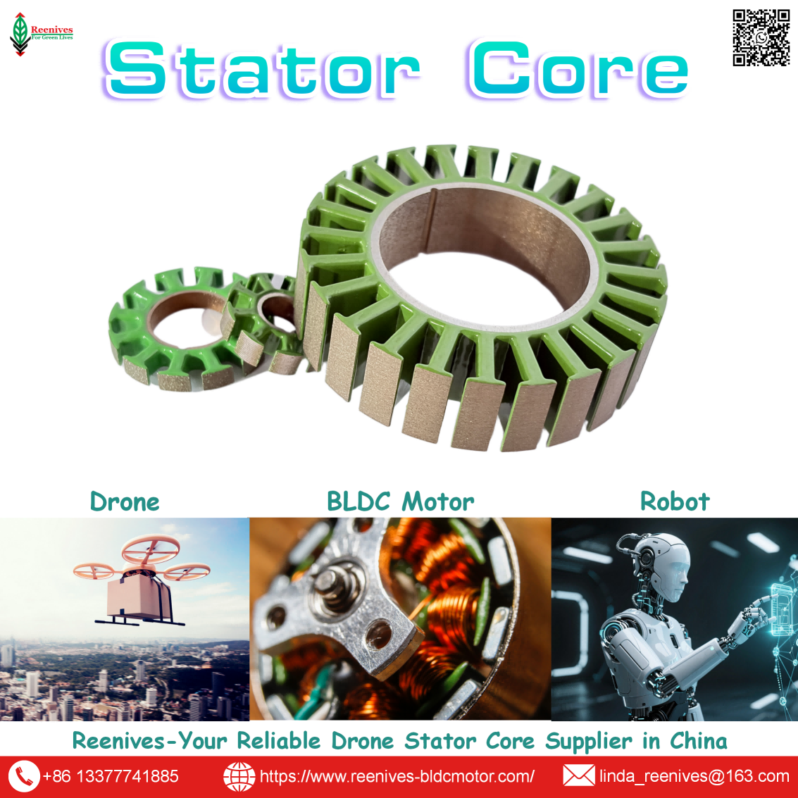
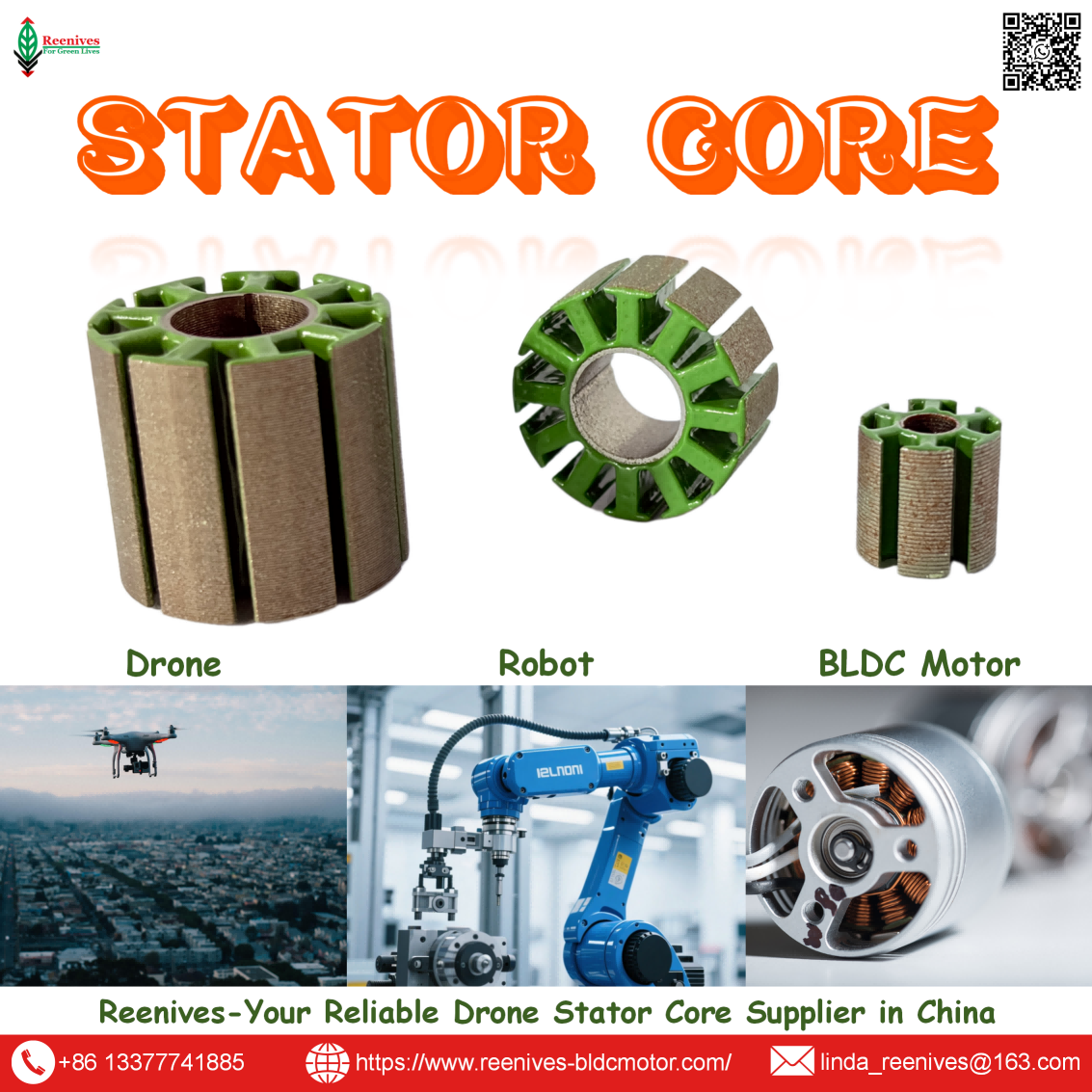
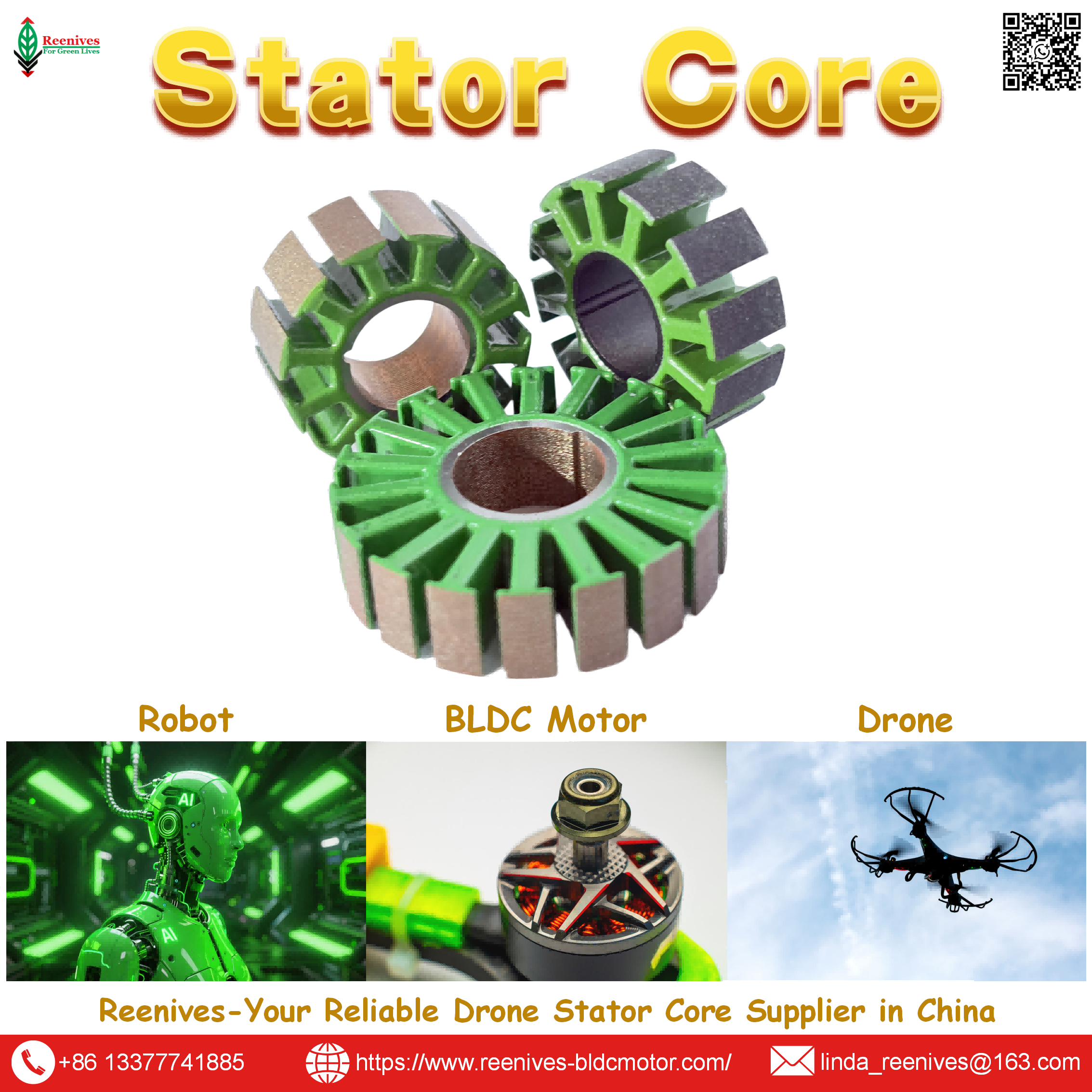
In an FPV brushless motor, the stator is the stationary laminated silicon steel stack whose slots hold copper windings. When current flows, the stator generates a rotating magnetic field. The rotor is the rotating outer bell that carries permanent magnets; the stator’s field pushes against those magnets, and the bell drives the propeller directly. FPV drones almost exclusively use outrunner motors, where the rotor is the outer bell spinning around the stator — a configuration chosen for high torque at lower RPM with no gearbox, which is what gives FPV its instant throttle response.
The phrase “stator rotor” therefore describes a relationship, not a bill of materials. The two components form a single electromagnetic circuit, and four properties belong to the pair rather than to either part alone:
- Air-gap geometry. The radial gap between stator bore and rotor magnet surface. It must be small for flux density and torque, but large enough for bearing play, thermal growth, and crash deformation. Reenives' published range is 0.2–1.0 mm, with production FPV motors running as tight as 0.1–0.12 mm.
- Concentricity. The gap must be uniform around the full bore. A non-uniform gap produces uneven magnetic pull, which loads the bearing. The eccentricity-to-bearing-failure chain starts here, and neither a stator-only nor a rotor-only inspection can detect it.
- Slot-pole alignment. The stator slot count and the rotor pole count must be a matched design decision. Common FPV combinations are 12S/14P and 9S/6P, and they must be matched between stator and rotor.
- Thermal expansion. At operating temperature, the stator stack and the rotor bell expand at different rates. A matched pair accounts for that in the cold-build gap; separately sourced parts may close the gap at temperature and rub.
Procurement translation: a quote for “stator” and a quote for “rotor” is not a matched-pair quote. The matched-pair quote names the air gap, the concentricity on the assembled pair, the slot-pole combination, the shared datum for bore and rotor OD, and the thermal-expansion allowance. Without those five fields, the buyer has outsourced the magnetic-circuit integration to their own assembly line — and inherited the mismatch risk.
Matched-Pair Configurations for FPV and UAV Motors: Outrunner, Inrunner, Segmented, IPM
Matched-pair manufacturing is not a single product. The configuration determines which half carries the tighter tolerance burden and which failure mode dominates at FPV speeds.
| Configuration | Stator Side | Rotor Side | Pair-Level Risk at FPV Speeds | Typical FPV Role |
|---|---|---|---|---|
| Outrunner pair | Stator inside; laminated core with concentrated winding | Outer bell with surface-mounted magnets; spins outside the stator | Air-gap uniformity around the full bore; bell roundness and balance | FPV racing and freestyle; direct propeller mounting, high torque, low inertia |
| Inrunner pair | Stator outside; rotor spins inside | Small-diameter rotor with magnets; higher speed | Rotor dynamic balance at very high RPM; bearing alignment | EDF and ducted-fan FPV and UAV applications |
| Segmented stator + matched rotor | Individual teeth wound separately, then assembled | Rotor matched to the assembled bore, not to individual segments | Segment-to-segment concentricity and phase balance | Higher slot fill; FPV motors where copper volume is the design driver |
| Surface-mount rotor pair | Standard laminated stator | Magnets bonded to the rotor surface with a retaining sleeve or epoxy | Magnet retention at overspeed; gap uniformity under centrifugal growth | High-torque FPV motors — the standard configuration |
| IPM (interior permanent magnet) pair | Stator designed for the reluctance profile | Magnets embedded inside rotor laminations | Magnet pocket tolerance and bridge thickness; pair-specific flux mapping | Higher reluctance torque and field weakening; less common in low-cost FPV |
The outrunner pair dominates FPV, and it is also the configuration where matched-pair supply matters most. The stator sits inside a rotating bell; the air gap is a thin annular band between the stator bore and the magnet inner surface. Any ovality in the stator stack, any out-of-roundness in the bell, and any off-centre bearing seat all converge on that band. At FPV speeds above 20,000 RPM, the published consequence is direct: “Any imbalance or air gap variation causes severe vibration that destroys bearings and degrades gyro performance”. A supplier who stamps both halves on the same lines and inspects the assembled gap is controlling the variable that a separate stator vendor and rotor vendor each control only partially.

Published Parameters and Verification: Air Gap, Tolerance, Stacking Factor, Core Loss, Rotor Balance, Magnet Grade
Air gap and critical dimensions
Reenives publishes a typical air gap of 0.2 mm – 1.0 mm for its drone stator-rotor pairs, with ±0.05 mm tolerance on critical dimensions including stator bore and rotor outer diameter. The air gap is a design balance: smaller gap raises flux density and torque for a given magnet grade, but it narrows the mechanical margin for bearing play, thermal growth, and crash deformation. Production FPV motors illustrate how far designers push this trade — a 2306 FPV motor lists a 0.10–0.12 mm gap, and a 2207 FPV motor lists a 0.1 mm ultra-small gap specifically to reduce magnetic loss and improve response. A matched-pair supplier sets the gap against the assembled rotor, not against two independent nominal drawings.
Concentricity and the FPV vibration chain
Reenives' engineering guidance notes that for high-RPM drone motors, “even a 0.05 mm air gap variation can cause measurable vibration and power loss”. On the rotor side, published FPV repair guidance sets a practical threshold: visible bell runout under 0.05 mm is acceptable, over 0.05 mm creates gyro noise, and over 0.1 mm is a problem. These two figures — 0.05 mm at the gap and 0.05 mm at the bell — are the same phenomenon viewed from opposite sides of the air gap. A matched pair holds both as one inspected dimension.
Stacking factor and core loss
Reenives publishes a stacking factor of ≥95% for its stator and rotor laminations, minimizing non-magnetic gaps between layers. Core loss for its standard stator and rotor laminations using 35WW250 silicon steel is published at ≤25 W/kg at 400 Hz / 1.0 T, material-dependent, with 0.20 mm grades available at lower loss. The measurement standard matters as much as the number: IEC 60404-2 specifies that the polarization waveform be sinusoidal and that no external stress be exerted on the specimen. That condition is exactly why a mill certificate is not a finished-stack report — stamping and stacking introduce stress and burrs that the Epstein specimen does not experience, and at FPV electrical frequencies those manufacturing-induced losses are amplified at the operating point where flight time and bearing life are decided.
Rotor balance and magnet grade
FPV rotor balance is specified against ISO 21940 quality grades; G6.3 is the common target for UAV propulsion, corresponding to a permissible vibration velocity of 6.3 mm/s at service speed. For FPV specifically, any visible bell runout over 0.05 mm is already a vibration problem. Magnet grade for FPV rotors is typically sintered NdFeB in the N42SH class, rated to approximately 150°C maximum operating temperature. FPV duty usually keeps rotor temperatures well below that limit, but continuous heavy-lift or agricultural use pushes closer to it — which is why higher-temperature grades such as N42UH are specified when rotor temperatures exceed 150°C. The pair-level thermal expansion allowance must account for the magnet’s operating temperature, not just its remanence.
Why separate sourcing amplifies the problem: the stator vendor controls burr height and stacking on the stator; the rotor vendor controls magnet pocket tolerance and balance on the rotor. Neither controls the assembled air gap, and neither is accountable for the combined eccentricity. At FPV speeds, the feedback loop is fast: uneven magnetic pull loads the bearing, bearing wear increases rotor eccentricity, and the increased eccentricity further distorts the air-gap flux. A matched-pair supplier makes the combined dimension a single inspection item — which is the only way it becomes a purchase-order requirement.
Application Profiles: Which Pair Parameter Binds Which FPV Mission
| FPV Mission Class | Binding Pair Parameter | Why | Specification to Write |
|---|---|---|---|
| FPV racing / high-RPM | Rotor balance and air-gap uniformity | Speeds above 20,000 RPM amplify any residual unbalance; a 0.05 mm gap variation becomes vibration and bearing load | Rotor balance to G6.3; air gap 0.2–1.0 mm with ±0.05 mm critical tolerance; concentricity ≤0.02 mm |
| Cinematic / freestyle FPV | Concentricity and cogging uniformity | Stable footage requires smooth torque; a matched pair suppresses cogging and vibration | 12S/14P low-cogging pair; concentricity ≤0.02 mm; matched bore/OD datum |
| Agricultural spraying | Coating integrity and thermal-expansion allowance | Continuous duty and chemical exposure; the pair must survive thermal cycling without gap closure | C5/C6 epoxy coating; air gap set with hot-state clearance; matched pair with thermal data |
| Industrial inspection / heavy-lift | Stacking factor and magnet grade | High continuous torque at large propeller diameter; flux density and magnet temperature are the limits | Stacking factor ≥95%; N42SH or higher-temperature grade; rotor balance at the assembled motor level |
The pattern is that the pair-level binding parameter changes with mission. FPV racing and cinematic platforms are limited by balance and concentricity because vibration is the visible failure. Agricultural platforms are limited by coating survival and thermal-expansion closure of the gap. Heavy-lift and inspection platforms are limited by flux density and magnet temperature, which are set by stacking factor and grade. A pair specification that names only one of these is under-specified for the missions where the others bind.

A 5-Step Qualification Workflow for a Matched Stator Rotor Supplier
- Ask for the pair drawing, not two part drawings. The pair drawing should show the assembled air gap, the stator bore and rotor OD datums, the slot-pole combination, and the concentricity tolerance measured on the assembled pair. If the supplier can only supply separate stator and rotor drawings, the integration risk remains with you.
- Specify the air gap with a hot-state allowance. Name the cold-build gap (Reenives typical 0.2–1.0 mm) and require the supplier to confirm that the gap remains positive at the maximum operating temperature, accounting for stator stack and rotor bell expansion. A gap that closes at temperature becomes a rub, and a rub becomes a field failure.
- Require concentricity on the pair, with a stated measurement method. Specify the tolerance and ask for the measurement setup: which datums, at what points around the bore, and whether the rotor is mounted during measurement. Reenives' published engineering guidance treats 0.05 mm air-gap variation as a vibration threshold on high-RPM drone motors — the concentricity requirement should be tighter than that if the application is FPV racing.
- Verify the stator-side manufacturing controls that the datasheet does not show. Ask for burr height limits, interlamination resistance results, stacking factor (≥95% per Reenives' specification), and core loss at the operating frequency measured on the finished stack, with the IEC 60404-2 test conditions stated. At FPV electrical frequencies, the difference between a clean stack and a burred stack is a measurable efficiency loss before the motor leaves the bench.
- Qualify the rotor side with balance and magnet data. Require rotor balance to ISO 21940 G6.3 or a stated milligram limit, and name the magnet grade with its working-temperature rating (N42SH ≈150°C is a common FPV baseline). If the rotor sits close to a hot stator under continuous duty, specify the next temperature class and require the supplier to confirm the pair’s thermal expansion allowance with the higher-grade magnet in place.
FAQ: Air Gap, Tolerance, Core Loss, Rotor Balance, and Eccentricity
Why must an FPV drone stator and rotor be supplied as a matched pair?
In an FPV outrunner, the stator and rotor form a single magnetic circuit separated only by the air gap. If they are sourced from separate vendors, the bore, the rotor outer diameter, the slot-pole alignment, and the concentricity are toleranced by two process chains with no shared datum. The result is a non-uniform air gap, which at FPV speeds above 20,000 RPM produces vibration that destroys bearings and degrades gyro performance. A matched pair holds the air gap and concentricity as one inspected dimension — Reenives publishes a typical 0.2 mm – 1.0 mm gap, ±0.05 mm tolerance on critical dimensions, and concentricity ≤0.02 mm on drone-grade cores.
Source: Reenives FPV stator rotor engineering guidance; Reenives stator and rotor pair specification table.
What air gap and tolerance should an FPV stator rotor pair hold?
Reenives publishes a typical air gap of 0.2 mm – 1.0 mm for drone stator-rotor pairs, with ±0.05 mm tolerance on critical dimensions. Production FPV motors often run tighter: a published 2306 FPV motor specifies a 0.10–0.12 mm air gap, and another FPV motor listing cites a 0.1 mm ultra-small gap for reduced magnetic loss. The gap must be small enough for flux density and torque, but large enough for bearing play, thermal growth, and crash deformation. A matched-pair supplier sets the gap against the assembled rotor, not against two independent nominal drawings.
Source: Reenives stator and rotor pair specification table; Karearea TOA LITE 2306 FPV motor specification; DolphinRC SkyRend 2207 FPV motor listing.
What core loss and stacking factor should an FPV stator rotor pair specify?
Reenives publishes a typical core loss of ≤25 W/kg at 400 Hz / 1.0 T for its standard stator and rotor laminations using 35WW250 silicon steel, measured on the finished stack, with 0.20 mm grades available at lower loss. The stacking factor is ≥95% for its stator and rotor laminations, minimizing non-magnetic gaps between layers. Core loss measurement follows the Epstein-frame principle of IEC 60404-2, which specifies a sinusoidal polarization waveform and no external stress on the specimen — a condition that raw steel experiences but a stamped and stacked core does not, which is why finished-stack data matters.
Source: Reenives FPV stator rotor specification table; IEC 60404-2 measurement conditions.
How is an FPV rotor balanced, and which magnet grade is standard?
FPV rotor balance is specified against ISO 21940 quality grades; G6.3 is the common target, corresponding to a permissible vibration velocity of 6.3 mm/s at service speed. For FPV, any visible bell runout over 0.05 mm is already a vibration problem, and over 0.1 mm is a defect. Magnet grade for FPV rotors is typically sintered NdFeB in the N42SH class, rated to approximately 150°C maximum operating temperature — appropriate for FPV duty where rotor temperatures usually stay well below that limit, but marginal for continuous heavy-lift use where N42UH or higher grades are specified.
Source: ISO 21940 G6.3 UAV balancing standard; published FPV bell runout thresholds; N42SH magnet grade temperature data.
What causes air-gap eccentricity, and how does it lead to bearing failure in an FPV motor?
Eccentricity can originate on the stator side from core ovality or incorrect rotor-to-stator positioning, and on the rotor side from a bent shaft, bearing wear, or crash-induced bell deformation. A non-uniform gap produces uneven magnetic pull, which loads the bearing. Bearing damage then increases rotor eccentricity, which further distorts the air-gap flux and amplifies electromagnetic vibration — a positive feedback loop. In FPV, this loop runs fast: a published motor spec notes that even a 0.05 mm air gap variation causes measurable vibration and power loss, and a bell runout over 0.05 mm creates gyro noise.
Source: Reenives high-RPM drone motor air-gap analysis; published FPV motor bell runout diagnostics.
Why do two FPV motors with the same 0.20 mm electrical steel perform differently?
Because the motor does not run on the steel datasheet — it runs on the finished core after punching, stacking, and assembly. Burrs left by improper die clearance or worn cutting edges can pierce the interlamination insulating coating during stacking, creating local conductive paths that produce additional eddy currents, higher core loss, and hot spots. Punching also introduces mechanical stress near narrow stator teeth, reducing permeability and increasing hysteresis loss. At FPV electrical frequencies — hundreds of hertz at 20,000+ RPM — these manufacturing-induced losses are amplified at exactly the operating point where flight time and bearing life are decided.
Source: Published analysis of core manufacturing errors in UAV motor stators; Reenives finished-stack verification practice.
Summary: Buy the Magnetic Circuit, Not Two Parts
“Stator rotor” is not two components on a BOM. In an FPV motor, it is one magnetic circuit separated by an air gap measured in tenths of a millimetre, and the pair-level properties — air-gap uniformity, concentricity, slot-pole alignment, and thermal expansion — cannot be delivered by a stator vendor and a rotor vendor working to separate drawings. The published data explains why the failure mode is so consistent: a 0.05 mm air-gap variation causes measurable vibration and power loss on high-RPM drone motors; production FPV motors run gaps of 0.10–0.12 mm, where that variation is a 40–50% change in the gap; and bell runout over 0.05 mm already shows up as gyro noise.
Reenives' published pair specifications are concrete: air gap 0.2–1.0 mm, ±0.05 mm critical tolerance, stacking factor ≥95%, core loss ≤25 W/kg at 400 Hz / 1.0 T on 35WW250 laminations measured per the IEC 60404-2 Epstein method, rotor balance to ISO 21940 G6.3, and N42SH magnets rated to approximately 150°C. The qualification question is not “who sells stator cores” and “who sells rotor bells.” It is “who manufactures the pair on one process chain, inspects the air gap as an assembled dimension, and publishes the manufacturing controls that keep burrs, stacking factor, and balance inside the specification.”
Need a matched stator rotor pair for an FPV or UAV motor program?
Reenives manufactures matched stator and rotor pairs on imported high-speed stamping lines with epoxy powder coating and dust-free workshops: air gap 0.2–1.0 mm, ±0.05 mm critical dimensions, stacking factor ≥95%, core loss ≤25 W/kg at 400 Hz / 1.0 T (35WW250, IEC 60404-2 method), rotor balance to G6.3, and N42SH magnets. Matched pairs are available for outrunner, inrunner, segmented, surface-mount, and IPM configurations. Send your slot-pole count, stack length, air-gap requirement, and rotor magnet grade for a sample evaluation and finished-pair inspection data.
WhatsApp: +86-13377741885
Email: linda_reenives@163.com
Official website: www.reenives-bldcmotor.com
Dongguan Runlu Motor Technology Co., Ltd.
Reenives — Drone Motor One-Stop Solution Supplier
Reenives is a professional drone stator core manufacturer, founded in 2022. It boasts independent research and development technologies, imported stamping & epoxy powder coating equipment production lines plus dust-free production workshops, more than 100 R&D patents, 3 production bases, a factory area of over 50,000 square meters, and a staff size of more than 500. From production to sales, we support bulk purchasing, private mould development, and sample making, and can provide tailor-made perfect solutions for your production and usage scenarios. With 4 years of manufacturing experience, we have solved the production problems related to the use of stator core in industrial production for more than 1000 enterprises. We can ship globally (with complete export qualifications). Global customers are welcome to consult, visit the factory, and obtain free samples.
Matched stator + rotor pairsAir gap 0.2–1.0 mm± 0.05 mm critical toleranceStacking factor ≥ 95%Core loss ≤ 25 W/kg @ 400 Hz / 1.0 TRotor balance G6.3N42SH magnetsGlobal export qualifications
What is Drone BLDC Stator?
Related Article