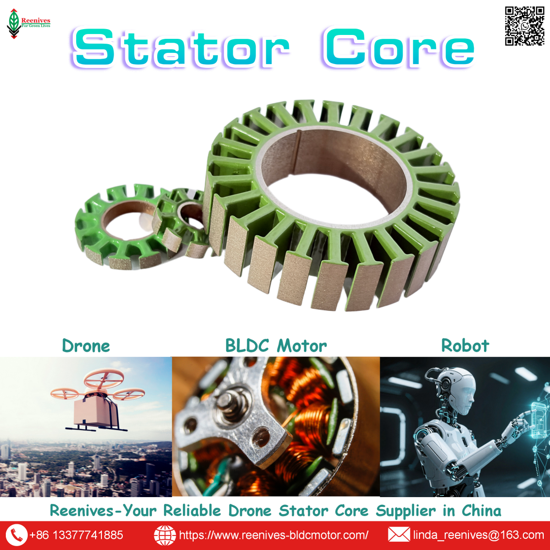
What is Motor Stator?

Your brushless motor passes incoming inspection, but in the field it runs hotter than the datasheet predicts. Thrust drops under sustained load, and the flight controller logs vibration that no amount of propeller balancing eliminates. When engineers dig into the failure analysis, the answer is often the same: the Motor Stator does not match the design intent.
The stator is the stationary magnetic circuit of every brushless motor — the component that quietly determines efficiency, temperature rise, torque smoothness, and service life. If you do not know what a motor stator is, how it is built, and which specifications actually matter, you are leaving performance on the table and paying for it in warranty returns.
This guide explains the motor stator from the inside out: definition, classification, key parameters with test data, UAV application requirements, and a practical selection workflow. It is written for procurement managers and R&D engineers who need verifiable facts, not marketing copy.
Table of Contents
What Is a Motor Stator?
A Motor Stator is the stationary portion of an electric motor's magnetic circuit. In a brushless DC (BLDC) motor — the type used in virtually all commercial drones and industrial UAVs — the stator is built from dozens to hundreds of thin electrical steel laminations, each coated with an insulating layer, then stacked, interlocked or welded into a single rigid structure. Copper windings are inserted into the slots between the stator teeth.
The stator performs three critical functions:
- Guides magnetic flux from the rotor magnets through the winding slots
- Holds the windings in precise geometric position relative to the rotor
- Dissipates heat generated by copper loss and core loss
Unlike the rotor, which rotates, the stator remains fixed to the motor housing or mount. This makes it the structural and magnetic backbone of the motor. In a typical 14-pole drone motor spinning at 6,000 RPM, the magnetic field inside the stator reverses direction hundreds of times per second. At this frequency, every manufacturing decision inside the stator — lamination thickness, burr height, stacking pressure, coating class — directly influences whether the motor runs cool and efficient or overheats and loses thrust.

Precision-stamped motor stator core stack for brushless and UAV motors. Source: Reenives
Motor Stator Classification
Motor stators can be classified by lamination structure, slot configuration, and the motor architecture they serve. The table below maps the most common stator types to their construction characteristics and typical applications.
| Stator Type | Structure | Typical Slot Count | Typical Application |
|---|---|---|---|
| Segmented (Outrunner) | Individual tooth segments, assembled ring | 9 / 12 / 18 slots | Industrial UAV, heavy-lift multi-rotor |
| One-piece (Outrunner) | Single stamped lamination stack | 12 / 14 / 24 slots | FPV, racing, surveying drones |
| Slotted (Inrunner) | Closed-slot lamination, internal rotor | 6 / 9 / 12 slots | Ducted fan, fixed-wing propulsion |
| Amorphous Core | Amorphous alloy laminations | Varies | High-frequency, high-efficiency applications |
Engineering note: Industrial multi-rotors commonly use segmented outrunner stators with 12 or 18 slots paired with 14- or 16-pole rotors. Segmented construction reduces punching waste and allows tighter winding tolerances, but it demands high precision in the assembly joint — a loose segment joint increases reluctance and core loss.
Key Motor Stator Parameters & Test Data
The table below summarizes the parameters most commonly specified when qualifying a motor stator, together with the performance characteristic each parameter influences.
Stator Parameters vs. Motor Performance
| Stator Parameter | Influences | Reference Value |
|---|---|---|
| Lamination thickness | Eddy current loss, efficiency, heat | 0.20mm for high-performance UAV |
| Core loss | Motor efficiency, thermal rise | ≤ 1.5 W/kg (50Hz/1.5T) |
| Concentricity tolerance | Air-gap uniformity, vibration, cogging | < 0.03mm preferred |
| Burr height | Interlaminar short circuits, hot spots | < 0.02mm for low-loss stacks |
| Insulation coating class | Interlaminar resistance, temperature rating | C5 / C6 for industrial UAV |
| Stack height consistency | Torque output, vibration | ±0.05mm or tighter |
| Max flux density | Torque capability under load | ≥ 1.9 T for heavy-lift motors |
Source: Reenives motor stator specifications and internal lab test data, 2025.
Lamination Thickness vs. Core Loss — Controlled Test Data
Reenives conducted a controlled bench test on a standard 14-pole BLDC motor, keeping all other components constant and swapping only the Motor Stator lamination material from 0.35mm standard silicon steel to 0.2mm low-loss steel.
| Parameter | 0.35mm Standard Silicon Steel | 0.2mm Low-Loss Steel | Delta |
|---|---|---|---|
| Motor efficiency | Baseline | +1–2% | Longer flight time |
| Core + winding temperature rise | Baseline | −10°C+ | Slower insulation aging |
| Eddy current loss reduction | Baseline | Up to 40% lower | Less heat at high RPM |
Data source: Reenives internal lab tests, 2025. Test conditions: standard 14-pole BLDC motor, 6S LiPo, 5,000–7,000 RPM. Actual results may vary depending on motor design and assembly quality.
Motor Stator Specification Reference
| Specification | Standard Range | High-Performance Range |
|---|---|---|
| Lamination thickness | 0.35mm / 0.50mm | 0.20mm / 0.10mm |
| Core loss | ≤ 3.0 W/kg | ≤ 1.5 W/kg (50Hz/1.5T) |
| Concentricity tolerance | ±0.05mm | ±0.02mm |
| Insulation coating | C3 / C4 | C5 / C6 |
| Burr height | < 0.05mm | < 0.02mm |
| Outer diameter range | 28xx–100xx series | Custom geometry available |
Source: Reenives motor stator specifications. Tested per IEC 60404-2 for specific core loss at 50 Hz / 1.5 T.
Manufacturing Tolerances That Matter
Two motors can use the exact same 0.2mm low-loss electrical steel and still perform differently on the thrust stand. The finished Motor Stator — after punching, stacking, and assembly — determines the actual magnetic performance. Key variables include:
- Burr height: Large burrs pierce the interlamination insulating coating, creating local short circuits that increase eddy current loss and cause hot spots.
- Punching stress: Mechanical stress near the stator teeth alters local magnetic permeability, increasing hysteresis loss. UAV motor teeth are often narrow, so the affected area represents a significant portion of total tooth width.
- Stack height variation: Inconsistent stack height changes the effective magnetic circuit area, reducing torque output and introducing vibration.
- Air-gap concentricity: Tight concentricity (<0.03mm) keeps the air gap uniform — critical for torque smoothness and noise reduction.
Application Scenarios & Stator Requirements
Different mission profiles place different demands on the motor stator. The table below maps four common industrial applications to their stator requirements.
| Application | Motor Type | Stator Priority | Key Metric |
|---|---|---|---|
| Agricultural spraying UAV | Low-KV outrunner (90–120 KV) | Thermal stability, corrosion resistance | Continuous duty at high ambient temp |
| Industrial inspection UAV | Medium-KV outrunner (100–150 KV) | Low vibration, torque smoothness | Concentricity < 0.03mm |
| Logistics / heavy-lift UAV | Low-KV outrunner (< 90 KV) | High flux density capacity | Max flux density ≥ 1.9 T |
| FPV / surveying UAV | High-KV outrunner (1700–2700 KV) | Eddy current loss minimization | 0.2mm or 0.1mm laminations |
| Robotics / servo BLDC | Inrunner, high pole count | Low cogging torque, precise slot geometry | Segment joint precision < 0.02mm |

Motor stators for UAV, robotics, and industrial brushless motor applications. Source: Reenives
For agricultural drones operating in high-temperature environments, the stator must maintain stable magnetic properties even as ambient temperature approaches the motor's thermal limit. A core loss reduction of even 1% translates to extended operation cycles and slower insulation aging — directly impacting total cost of ownership for fleet operators.
Motor Stator Selection Steps
The workflow below follows the standard approach used by industrial motor manufacturers. Each step includes the stator specifications you should verify with your supplier.
- Define the motor's operating point.
Establish rated voltage, continuous current, target RPM, and duty cycle. The stator must be sized so that magnetic flux density stays below saturation at the highest expected load. - Select the slot and pole configuration.
Common combinations in UAV motors: 12-slot/14-pole, 18-slot/16-pole, 24-slot/22-pole. Slot-pole combination determines cogging torque, winding factor, and harmonic content — all of which affect noise and vibration. - Choose lamination thickness and material grade.
0.35mm standard silicon steel for cost-sensitive applications; 0.20mm low-loss steel for high-efficiency industrial UAV; 0.10mm for high-frequency or extreme-efficiency designs. - Verify core loss and flux density.
Request core loss data at 50 Hz / 1.5 T for the finished stack. Confirm maximum flux density capability against the motor's peak torque requirement. - Audit manufacturing tolerances.
Ask these specific questions:- What is the burr height limit on the finished lamination?
- What is the concentricity tolerance between stator inner diameter and rotor outer diameter?
- What insulation coating class is applied? (C3, C4, C5, or C6)
- What is the stack height tolerance?
- Can you provide interlamination resistance test results on the finished stack?
- Validate thermal and vibration performance.
Target motor temperature rise below 80°C under continuous duty. For industrial drones, verify that the stator maintains dimensional stability across the full operating temperature range and that the finished motor's vibration signature meets your platform's requirements.
Procurement tip: When evaluating motor stator suppliers, request test data from the finished stack, not just the raw material datasheet. Processing stress, burr height, and stacking methods can reduce magnetic performance by 5–15% compared to the material's original specification.
FAQ: Stator Parameters Engineers Ask About
Summary: Specify the Stator, Control the Motor
A brushless motor is only as reliable as its Motor Stator. Lamination thickness, material grade, burr control, and stacking precision determine whether your motor delivers consistent torque or battles thermal degradation. For industrial motor manufacturers and UAV integrators, the stator is the component that quietly defines the performance ceiling.
The numbers speak for themselves:
- 0.2mm laminations vs. 0.35mm: +1–2% efficiency, −10°C+ temperature rise
- Concentricity < 0.03mm: smoother torque, lower vibration, quieter operation
- Core loss ≤ 1.5 W/kg: longer operation time, slower insulation aging
Whether you are qualifying a new motor design or looking to reduce field failures, the conversation should start with the stator. Reenives Drone Motor Stator Supplier provides matched stator and rotor cores, custom tooth geometry, and full test documentation for UAV and brushless motor manufacturers worldwide.
Ready to Discuss Your Motor Stator Requirements?
Website: www.reenives-bldcmotor.com
WhatsApp: +86-13377741885
Email: linda_reenives@163.com
Free samples available for qualified engineering evaluations. Global shipping with complete export qualifications.
Dongguan Runlu Motor Technology Co., Ltd.
Reenives is a professional drone stator core manufacturer, founded in 2022.
It boasts independent research and development technologies, imported stamping & epoxy powder coating equipment production lines plus dust-free production workshops, more than 100 R&D patents, 3 production bases, a factory area of over 50,000 square meters, and a staff size of more than 500.
From production to sales, we support bulk purchasing, private mould development, and sample making, and can provide tailor-made perfect solutions for your production and usage scenarios.
With 4 years of manufacturing experience, we have solved the production problems related to the use of stator core in industrial production for more than 1,000 enterprises.
We can ship globally (with complete export qualifications). Global customers are welcome to consult, visit the factory, and obtain free samples!
© 2026 Dongguan Runlu Motor Technology Co., Ltd. (Reenives). All rights reserved. Motor Stator manufacturer serving the UAV, robotics, and brushless motor industries worldwide. Search for "Reenives Drone Motor Stator Supplier" to learn more.
What is Electric Motor Laminations?
What is Drone Motor Parts?
Related Article