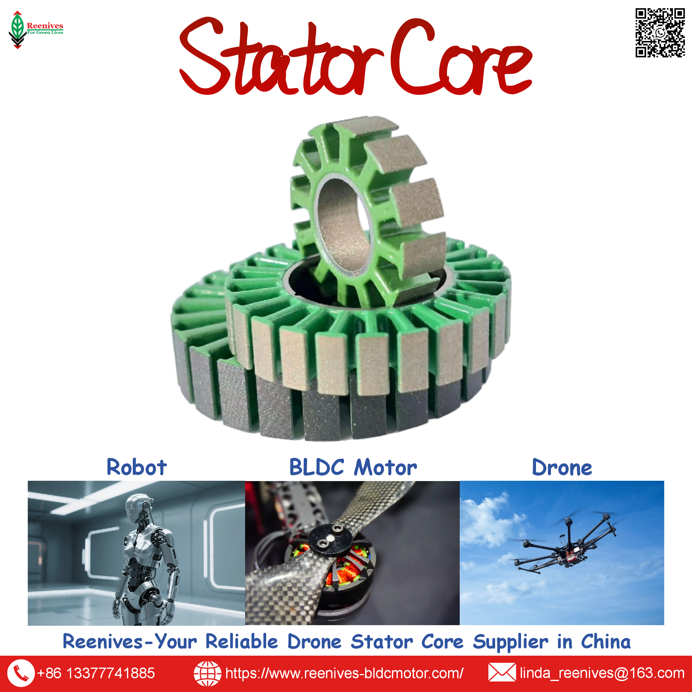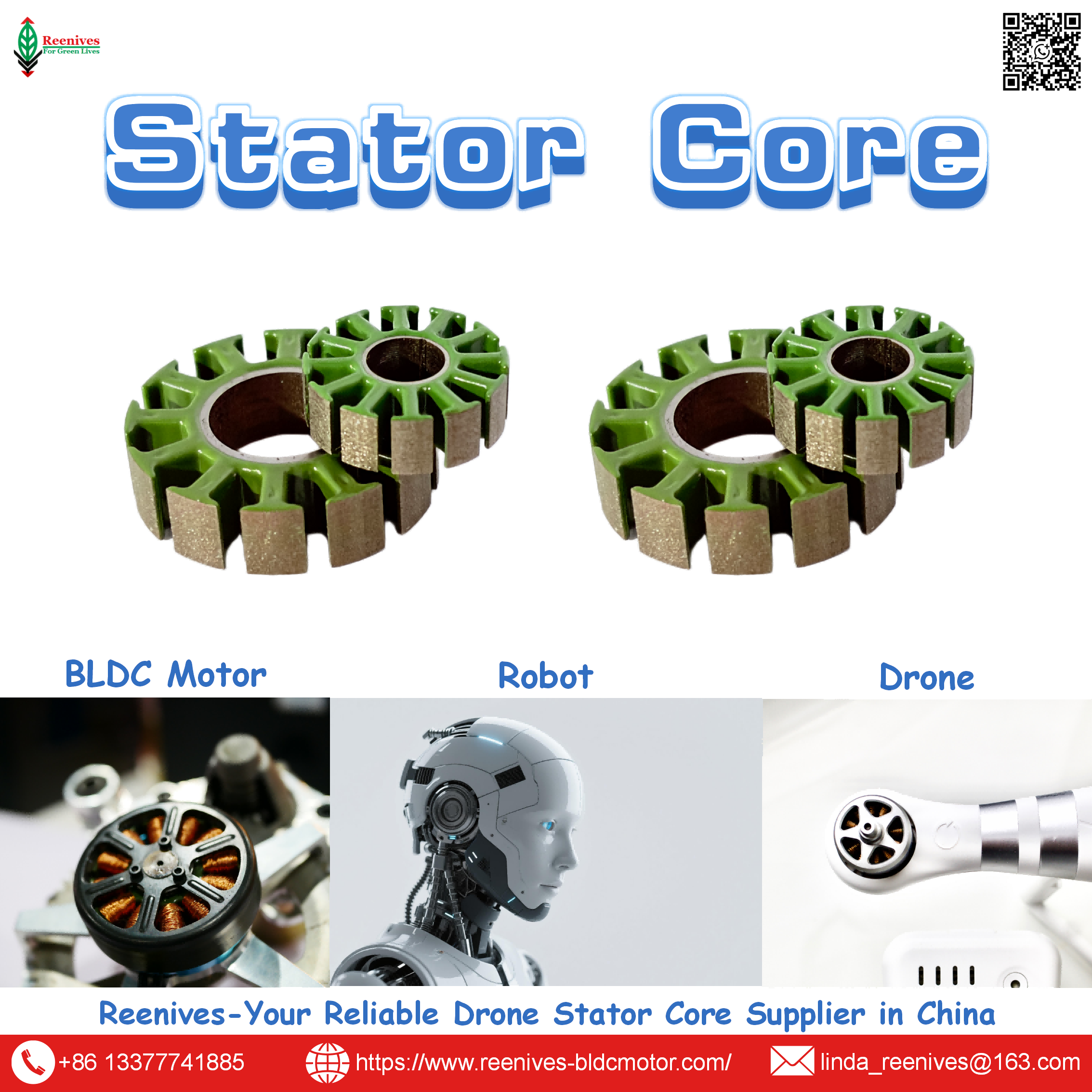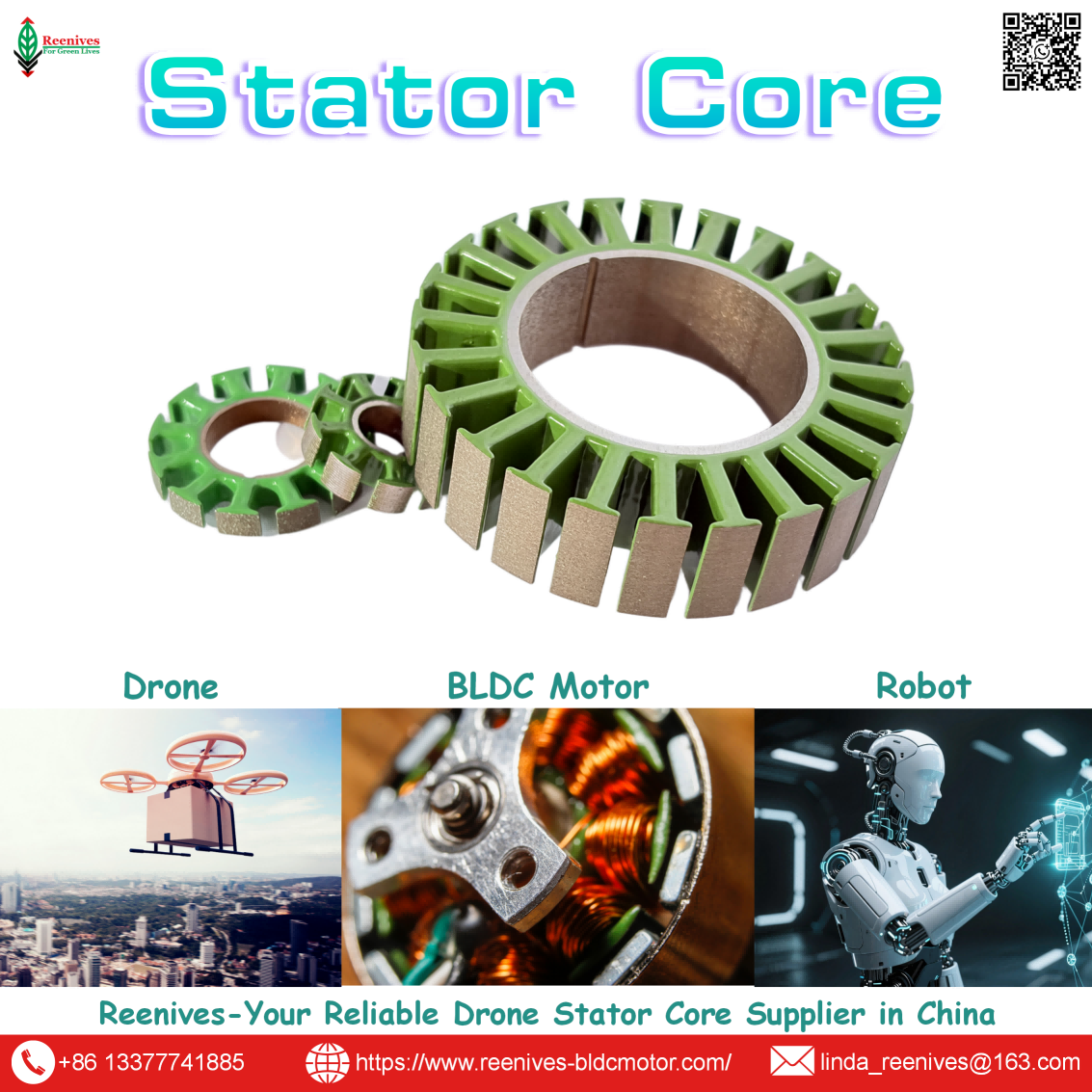
Reenives: Global Leading BLDC Drone UAV FPV Motor Winding Stator Supplier

Winding Stator for BLDC Drone, UAV, and FPV Motors: The Core Specification Behind Every Coil
Two winding stators, same wire gauge, same turn count, same 12N14P layout — and one flies for eighteen minutes while the other sags at minute nine. The difference is almost never the winding itself. It is the stator core underneath: the lamination grade, the stacking factor, the burr height, the slot opening geometry, and the coating that determines whether the winding survived the process at all. A winding stator is a core plus copper, but the core sets the ceiling on what the copper can achieve. Buyers who source the wound assembly without auditing the core are purchasing a result they cannot predict.
The published numbers show how much performance sits in that core. A 0.35 mm lamination grade runs at roughly 28–35 W/kg at 1.0 T / 400 Hz; a 0.20 mm grade runs at roughly 10–14 W/kg. Reenives publishes its drone winding stator cores at ≤8.5 W/kg at 1.0 T / 400 Hz, with a stacking factor of ≥97.5%, burr height <0.03 mm, critical-dimension tolerance ±0.05 mm, and a uniform epoxy coating. Those are not catalogue decorations — they are the parameters that determine whether a winder can reach 75% slot fill, whether the enamel survives ±0.05 N tension, and whether the finished winding stator holds its KV through a season of flights.
This guide treats the winding stator as what it is in procurement terms: a two-part specification where the core constrains the winding. It defines the difference between a bare core and a wound stator, separates the winding configurations that matter for drone, UAV, and FPV motors, presents the published core and winding parameters with their standards, maps the configuration to mission profiles, and closes with a five-step sourcing workflow. Every figure below is traceable to a published specification or a named measurement standard.
In this guide — jump to the section your project needs:
- What Is a Winding Stator? The Core-Plus-Copper Definition and Why the Core Comes First
- Winding Stator Configurations: 12N14P, 9N12P, 18N24P, 24N28P and Flyer vs Needle
- Published Parameters: Core Loss, Stacking Factor, Burr, Tolerance, Tension, Slot Fill, and Electrical Test
- Application Profiles: Which Winding Stator Configuration Binds Which Drone, UAV, and FPV Mission
- A 5-Step Winding Stator Sourcing Workflow
- FAQ: Winding Stator Definition, Core Influence, Specifications, 12N14P, Electrical Test, and Coating
- Summary: Buy the Core and the Coils Together
What Is a Winding Stator? The Core-Plus-Copper Definition and Why the Core Comes First
A winding stator is a stator core that has received its copper windings. The bare core is a stack of individually insulated electrical steel laminations with slot geometry but no copper. The winding stator is that core after enameled copper wire has been inserted into its slots, arranged in a defined pattern, and terminated. The two are produced by different processes, audited against different specifications, and fail in different ways.
| Component | What It Is | Audit Specifications | Failure Mode If Deficient |
|---|---|---|---|
| Stator core (bare) | Stacked, insulated electrical steel laminations with slot geometry | Lamination grade and thickness; core loss per IEC 60404-2; stacking factor; burr height; concentricity; coating class | Elevated iron loss → stator heat; loose stack → lost flux density; eccentric bore → vibration and bearing load |
| Winding | Enameled copper wire inserted into slots and terminated | Tension window; wire placement accuracy; turn count; slot fill factor; phase resistance balance | Enamel micro-damage → turn-to-turn short; loose coil → vibration; uneven resistance → torque ripple |
| Winding stator (finished) | Core plus winding, electrically tested | Hi-Pot; 3-phase resistance; surge waveform; insulation resistance; polarity | Latent turn-to-turn short that passes a spin test and fails in flight |
Sources: Reenives drone stator core specification (lamination grade, core loss, stacking factor, burr, concentricity, coating); published winding process parameters (tension, placement, slot fill); JYSTATOR 100% electrical test specification (Hi-Pot, 3-phase resistance, surge waveform).
The reason the core comes first in the audit is that the winding cannot escape the core’s physical constraints. Slot opening geometry determines whether an automated flyer or needle can enter and how much copper can be packed in — typically the winding space must leave at least three times the wire diameter for the tool to pass. Insulation coating integrity determines how much winding tension the enamel can survive before a turn-to-turn short occurs. Burr height on the lamination edges can pierce the coating during winding and create a latent short. Concentricity between stator bore and rotor outer diameter determines the air gap the finished winding stator will operate across. A perfect winding on an out-of-tolerance core produces a motor that overheats, vibrates, or fails early — and every one of those outcomes will be attributed to the winding.
Procurement translation: a winding stator quotation that names only the wire gauge and the turn count has described half the product. The specification must also carry the core parameters: lamination grade and thickness, core loss at a defined test point per IEC 60404-2, stacking factor, burr height, concentricity, coating class, and slot/pole geometry. A supplier who can restate all of them is describing a winding stator. A supplier who can restate only the winding is describing a coil.
Winding Stator Configurations: 12N14P, 9N12P, 18N24P, 24N28P and Flyer vs Needle
Slot-pole configurations for drone, UAV, and FPV motors
The slot-pole combination defines the electromagnetic structure the winding must fit into, and it determines the winding factor, the cogging profile, and the manufacturability of the winding stator.
| Configuration | Slots | Poles | Winding Character | Typical Application |
|---|---|---|---|---|
| 12N14P | 12 | 14 | Fractional-slot concentrated winding, q ≈ 0.286; fundamental winding factor ≈ 0.933; very low cogging | FPV, multirotor, and general UAV propulsion — the drone default |
| 9N12P | 9 | 12 | Fractional-slot; lighter stator with higher speed bias | Small outrunners and lightweight FPV builds |
| 18N24P | 18 | 24 | Higher slot count; different torque ripple profile | Larger outrunners and industrial UAV platforms |
| 24N28P | 24 | 28 | High slot count; smooth torque character | Heavy-lift, eVTOL, and high-torque industrial propulsion |
Sources: Published 12N14P winding analysis (q = 12/(14×3) ≈ 0.286; winding factor ≈ 0.933; low cogging); Reenives slot/pole configuration record (9N12P, 12N14P, 18N24P, 24N28P).
For a 12N14P machine, slots per pole per phase calculate to q = 12 ÷ (14 × 3) ≈ 0.286, making it a fractional-slot concentrated winding. Each coil wraps primarily around a single tooth, shortening the end winding and reducing the inactive copper that adds weight and resistance without contributing to electromagnetic conversion. The slight slot-pole asymmetry means the magnets never align with all teeth simultaneously, which is why 12N14P delivers very low cogging torque. That combination — high winding factor, low cogging, short end turns, and a compact outrunner package — is why it dominates drone propulsion.
Flyer versus needle winding architecture
| Architecture | Mechanism | Slot Orientation | Winding Stator Fit |
|---|---|---|---|
| Flyer (external winding) | High-speed rotating fork orbits the stator and guides wire into slots | Outward-facing slots | Mainstream for 12N14P and other drone outrunners; published speeds of 2,000–5,000 rpm for the general architecture, 800–1,500 rpm for fine drone wire |
| Needle (internal winding) | Precision nozzle reciprocates through narrow slot openings | Inward-facing slots | Pumps, power tools, internal-slot stators; requires carbide or ceramic-coated nozzle to protect enamel |
Sources: Published flyer versus needle selection guidance (slot orientation determines architecture); drone-specific winding data (flyer for outrunners; fine wire 800–1,500 rpm); Vacuz needle nozzle requirements (carbide/ceramic coating).
The architecture is not a preference — it is dictated by the slot orientation. In a drone outrunner the stator sits inside and the slots face outward, so a flyer that orbits the stator has a clear path to the slots. A needle machine cannot reach an outward-facing slot efficiently, and a flyer cannot wind an inward-facing slot at all. That is why the winding stator specification must name the slot orientation before the machine or the supplier is selected.
Published Parameters: Core Loss, Stacking Factor, Burr, Tolerance, Tension, Slot Fill, and Electrical Test
Core side: the published Reenives winding stator specification
Reenives publishes its drone winding stator cores with a complete parameter set measured on the finished part, not inferred from a mill certificate. The published values are core loss ≤8.5 W/kg at 1.0 T / 400 Hz on 0.20 mm silicon steel, with a stacking factor ≥97.5%, burr height <0.03 mm, critical-dimension tolerance ±0.05 mm, and a uniform epoxy coating. Slot/pole configurations include 9N12P, 12N14P, 18N24P, and 24N28P. The comparison point matters: a 0.35 mm grade runs at roughly 28–35 W/kg at the same test point, and a generic 0.20 mm grade falls in the 10–14 W/kg range. The published ≤8.5 W/kg is therefore not a generic 0.20 mm claim — it is a specific grade and process result.
| Parameter | Reenives Published Value | Test Standard / Method | What It Controls in the Winding Stator |
|---|---|---|---|
| Core loss | ≤8.5 W/kg @ 1.0 T / 400 Hz | IEC 60404-2 (Epstein frame) | Iron heat generated at the operating electrical frequency |
| Lamination thickness | 0.20 mm silicon steel | Micrometer, batch sampling | Eddy-current loss scaling with thickness squared |
| Stacking factor | ≥97.5% | Weight / dimension method | Effective flux density of the finished stack |
| Burr height | <0.03 mm | Optical comparator edge scan | Prevents burrs piercing the coating during winding |
| Critical tolerance | ±0.05 mm | Vision / metrology on finished core | Consistent seating in the winding fixture; air-gap geometry |
| Coating | Epoxy, uniform | Visual + dielectric check | Interlaminar insulation surviving winding tension and thermal cycling |
| Slot/pole geometry | 9N12P · 12N14P · 18N24P · 24N28P | Dimensional inspection | Winding pattern, winding factor, cogging profile |
Source: Reenives drone stator core / winding stator specification (core loss, lamination thickness, stacking factor, burr, tolerance, coating, slot/pole configurations); IEC 60404-2 Epstein-frame method.
Winding side: tension, placement, slot fill
Published winding process data places tension fluctuation within ±0.05 N and wire placement accuracy better than ±0.03 mm. Traditional manual or low-tier machine winding yields a copper slot fill factor of roughly 30–40%; advanced multi-axis CNC with layered or interleaved patterns reaches 75%, with one supplier reporting 80% using electronic cam non-linear linkage control. The ceiling is set by the core: the winding space must typically leave three times the wire diameter for the tool to enter, so a small slot opening designed for low cogging limits the achievable fill. Slot geometry and winding process are a coupled decision.
Finished side: 100% electrical test
Published drone stator test specifications call for 100% electrical performance testing on every winding stator, covering Hi-Pot for insulation integrity, three-phase resistance for winding consistency, and surge waveform testing for turn-to-turn short circuits. Surge testing is the differentiator: a turn-to-turn short can leave phase resistance within tolerance while generating a hot spot under load, so a resistance check alone passes the defect. Four-wire resistance measurement is used for accuracy, with typical tolerance around ±0.5%.
The silent failure mode: a winding stator with a coating that was already thin at the slot edge, a burr that pierced it during wire insertion, or an enamel micro-damage from tension fluctuation will pass the initial electrical test. It will then degrade under thermal cycling and vibration until the insulation breaks down — often after hundreds of flights. That is why the core specification and the electrical test are not alternatives; the core prevents the damage, and the test detects what the core could not prevent. A supplier who offers only one of the two is selling half the assurance.
Application Profiles: Which Winding Stator Configuration Binds Which Drone, UAV, and FPV Mission
| Mission Class | Typical Configuration | Binding Winding Stator Parameter | Specification to Write |
|---|---|---|---|
| FPV racing / freestyle | 12N14P, 0.20 mm, fine wire | Core loss at high frequency + surge test coverage | ≤8.5 W/kg @ 1.0 T / 400 Hz; 100% surge waveform test; burr <0.03 mm |
| Cinematic / inspection FPV | 12N14P, 0.20 mm, moderate wire | Concentricity + phase resistance balance | ±0.05 mm critical tolerance; 3-phase resistance within tolerance |
| Agricultural spraying UAV | Larger outrunner, thicker wire or parallel strands | Coating integrity + slot fill | Uniform epoxy coating; fill target matched to slot opening; 100% Hi-Pot |
| Heavy-lift / logistics UAV | 18N24P or 24N28P, thick stack | Stacking factor + torque density | Stacking factor ≥97.5%; published core loss on finished stack |
| eVTOL / high-torque propulsion | 24N28P, large stator | Stacking factor + concentricity at scale | ≥97.5% stacking; ±0.05 mm tolerance verified on full-diameter bore |
The pattern is that the binding parameter tracks the mission’s dominant failure mechanism. FPV racing binds on core loss and surge coverage because high electrical frequency amplifies iron heat and the consequences of a latent short are severe. Cinematic and inspection platforms bind on concentricity and phase balance because vibration reaches the payload before it reaches the motor. Agricultural platforms bind on coating and slot fill because the duty cycle is long, wet, and current-heavy. Heavy-lift and eVTOL bind on stacking factor and dimensional tolerance at scale, because continuous torque and large diameters expose both.
A 5-Step Winding Stator Sourcing Workflow
- Specify the core before the winding. Write the lamination grade and thickness, core loss at a defined test point per IEC 60404-2, stacking factor, burr height, critical tolerance, coating class, and slot/pole geometry. For a drone programme the reference set is 0.20 mm silicon steel, ≤8.5 W/kg @ 1.0 T / 400 Hz, stacking factor ≥97.5%, burr <0.03 mm, tolerance ±0.05 mm, epoxy coating. A winding quotation without these lines is not comparable to one that includes them.
- Confirm the slot orientation and the winding architecture it requires. Outward-facing slots (drone outrunner) point to flyer winding; inward-facing slots point to needle winding. Name the architecture in the specification so the winding and the core are matched from the start rather than discovered incompatible at the trial wind.
- Set the slot fill target against the core’s actual slot opening. Published fill ranges from 30–40% for manual and low-tier winding to 75–80% with advanced CNC layered patterns. The ceiling is geometric: roughly three times the wire diameter of entry clearance is needed. Ask for the fill achieved on a sample with the production wire, not a theoretical maximum.
- Require 100% electrical testing and review the evidence. Specify Hi-Pot, three-phase resistance, and surge waveform testing on every winding stator. Ask for a recent record showing a unit that failed surge testing and was rejected — a supplier with no rejected units is either perfect or not testing. Confirm the test data is bound to a batch or serial number so a field failure can be traced to a winding run.
- Run a trial wind with production stators and production wire. Send two to three stator cores and the exact wire specification to the winding supplier, have them wind the sample, and inspect wire lay, slot fill, enamel condition at the slot edges, and the electrical test results before committing to volume. This is the step that reveals whether the core and the winding are genuinely matched, and it is far cheaper than discovering the mismatch after the first production lot.
FAQ: Winding Stator Definition, Core Influence, Specifications, 12N14P, Electrical Test, and Coating
What is a winding stator, and how is it different from a bare stator core?
A bare stator core is a stack of insulated electrical steel laminations with slot geometry but no copper. A winding stator is that core after enameled copper wire has been inserted into its slots and terminated. The distinction matters for sourcing because the two are produced by different processes and audited against different specifications: the core is judged on lamination grade, core loss, stacking factor, burr height, concentricity, and coating integrity, while the winding is judged on tension, wire placement accuracy, turn count, phase resistance balance, and surge withstand. A supplier who provides only the wound assembly still depends on the core’s dimensional and coating quality — a compromised core produces a defective winding stator regardless of how well the winding itself is executed.
Source: Reenives stator core specification (core-side parameters); published winding process parameters (winding-side parameters).
Why does the stator core matter so much if the winding is what carries current?
Because the core sets the physical and electromagnetic ceiling the winding can work within. Slot opening geometry determines whether an automated flyer or needle can enter and how much copper can be packed in; typically three times the wire diameter of entry clearance is required. Insulation coating integrity determines how much winding tension the enamel can survive before a turn-to-turn short occurs. Burr height on lamination edges can pierce the coating during winding and create a latent short. Concentricity between stator bore and rotor outer diameter determines the air gap that the wound stator will operate across. A perfect winding on an out-of-tolerance core produces a motor that overheats, vibrates, or fails early.
Source: Published winding process constraints (slot opening, coating integrity, burr effect); Reenives concentricity specification.
What stator core specifications should accompany a winding stator order?
Name lamination thickness and grade, core loss at a defined test point, stacking factor, burr height, concentricity, coating class, and slot/pole geometry together. Reenives publishes drone stator cores at 0.20 mm silicon steel with core loss ≤8.5 W/kg at 1.0 T / 400 Hz, stacking factor ≥97.5%, burr height <0.03 mm, critical-dimension tolerance ±0.05 mm, and epoxy coating, in slot/pole configurations including 9N12P, 12N14P, 18N24P, and 24N28P. A winding stator quotation that names only the wire gauge and turn count has not specified the component that determines whether the winding survives.
Source: Reenives drone stator core specification (0.20 mm, ≤8.5 W/kg, ≥97.5% stacking, <0.03 mm burr, ±0.05 mm tolerance, epoxy coating, slot/pole configurations).
What is the 12N14P configuration, and why is it common in drone winding stators?
12N14P means 12 stator slots and 14 rotor poles. For a three-phase machine, slots per pole per phase calculate to q = 12 ÷ (14 × 3) ≈ 0.286, making it a fractional-slot concentrated winding. Each coil wraps primarily around a single tooth, shortening the end winding and reducing inactive copper. For a typical single-layer concentrated winding, the fundamental winding factor reaches approximately 0.933. The slight asymmetry between slot and pole count means the magnets never align with all teeth simultaneously, which reduces cogging torque. The combination is common because it balances torque, smoothness, and manufacturability in a compact outrunner package.
Source: Published 12N14P winding analysis (q ≈ 0.286; winding factor ≈ 0.933; concentrated winding; cogging reduction from slot-pole asymmetry).
What electrical tests should a finished winding stator pass?
Published drone stator test specifications call for 100% electrical performance testing on every wound stator, covering Hi-Pot for insulation integrity, three-phase resistance for winding consistency, and surge waveform testing for turn-to-turn short circuits. Broader stator test frameworks add insulation resistance, winding resistance, phase balance, and polarity or rotation checks. Surge testing is the critical differentiator: a turn-to-turn short can leave phase resistance within tolerance while generating a hot spot under load, so a resistance check alone passes the defect. Four-wire resistance measurement is used for accuracy, with typical tolerance around ±0.5%.
Source: JYSTATOR drone stator winding specification (100% Hi-Pot, 3-phase resistance, surge waveform); published stator test framework (insulation resistance, phase balance, polarity); four-wire measurement and ±0.5% tolerance.
How does coating integrity affect winding stator reliability in the field?
The interlamination coating is the electrical barrier that prevents adjacent laminations from shorting to each other. During winding, tension and tool contact can abrade or pierce that coating; during operation, thermal cycling and vibration stress it further. Reenives specifies epoxy coating on its drone stator cores precisely because a uniform, pinhole-free layer survives the winding process and the thermal duty cycle. A coating that is thin or has voids can produce a winding stator that passes the initial electrical test and fails after hours of flight as the insulation degrades. Coating class, coverage, and adhesion are therefore part of the winding stator specification, not a cosmetic detail.
Source: Reenives stator core coating specification (epoxy, uniform); published winding stress effects on interlamination insulation.
Summary: Buy the Core and the Coils Together
A winding stator is a core plus copper, and the core sets the ceiling on what the copper can achieve. The published specification set is concrete: 0.20 mm silicon steel, core loss ≤8.5 W/kg at 1.0 T / 400 Hz, stacking factor ≥97.5%, burr height <0.03 mm, critical tolerance ±0.05 mm, and uniform epoxy coating, in 9N12P, 12N14P, 18N24P, and 24N28P configurations. Those values determine whether a winder can reach 75% slot fill at ±0.05 N tension without damaging the enamel, and whether the finished winding stator holds its KV through a season of thermal cycling.
The comparison points make the value visible. A 0.35 mm lamination grade runs at roughly 28–35 W/kg at the same test point, and a generic 0.20 mm grade falls in the 10–14 W/kg range. Manual and low-tier winding lands at 30–40% slot fill. And a turn-to-turn short that leaves resistance within tolerance will pass a resistance check and fail the surge waveform test — which is why 100% surge testing belongs in the winding stator specification alongside the core parameters.
The sourcing takeaway is that the winding stator should be bought as a matched pair of specifications, not as a single line item. Name the core parameters that prevent the damage, and name the electrical test that detects what the core could not prevent. A supplier who can restate both, and who can show a rejected unit from their own inspection process, is describing a winding stator. A supplier who can only quote a wire gauge and a turn count is describing a coil.
Specifying a winding stator for a BLDC drone, UAV, or FPV motor programme?
Reenives manufactures precision stamped stator cores for winding: 0.20 mm silicon steel, core loss ≤8.5 W/kg at 1.0 T / 400 Hz, stacking factor ≥97.5%, burr height <0.03 mm, critical tolerance ±0.05 mm, and uniform epoxy coating, in 9N12P, 12N14P, 18N24P, and 24N28P slot/pole configurations. Matched stator-rotor pairs, private mould development, and free samples are available for qualified engineering evaluations.
WhatsApp: +86-13377741885
Email: linda_reenives@163.com
Official website: www.reenives-bldcmotor.com
Dongguan Runlu Motor Technology Co., Ltd.
Reenives — Drone Motor One-Stop Solution Supplier
Reenives is a professional drone stator core manufacturer, founded in 2022. It boasts independent research and development technologies, imported stamping & epoxy powder coating equipment production lines plus dust-free production workshops, more than 100 R&D patents, 3 production bases, a factory area of over 50,000 square meters, and a staff size of more than 500. From production to sales, we support bulk purchasing, private mould development, and sample making, and can provide tailor-made perfect solutions for your production and usage scenarios. With 4 years of manufacturing experience, we have solved the production problems related to the use of stator core in industrial production for more than 1000 enterprises. We can ship globally (with complete export qualifications). Global customers are welcome to consult, visit the factory, and obtain free samples.
0.20 mm silicon steelCore loss ≤8.5 W/kg @ 1.0 T / 400 HzStacking factor ≥97.5%Burr <0.03 mmCritical tolerance ±0.05 mmUniform epoxy coating9N12P · 12N14P · 18N24P · 24N28PGlobal export qualifications
Reenives: Global Leading Drone Motor Production Line Supplier
Related Article