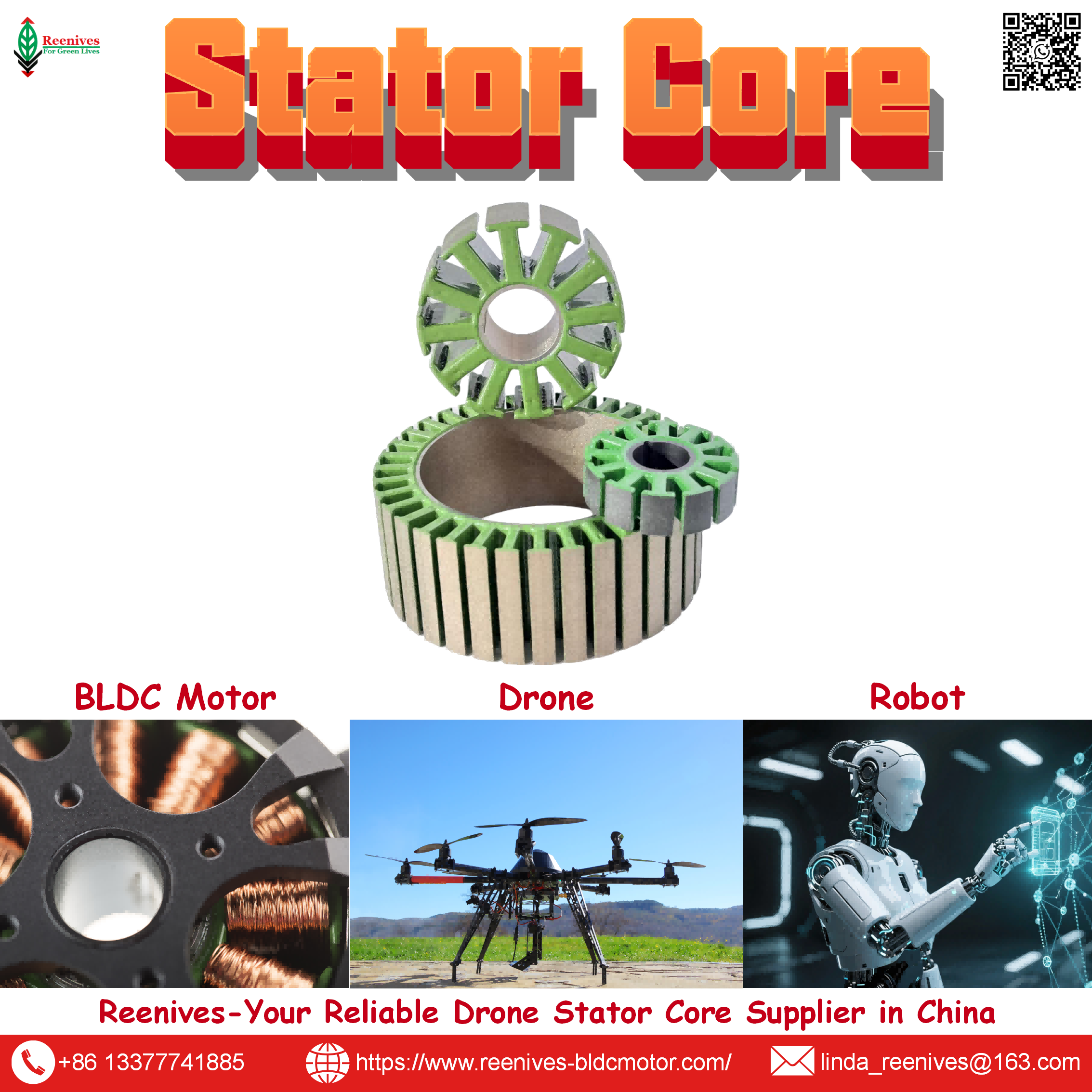
Parameters of Drone Motor Stator Core

Parameters of Drone Motor Stator Core: The Magnetic, Dimensional, Insulation, and Electromagnetic Values That Decide Performance
A stator core datasheet that lists only “0.20 mm silicon steel” has described one parameter — and it is not even the parameter that decides whether the motor holds its thrust curve. The thickness is an input. The core loss at the operating electrical frequency is the output that becomes heat. The stacking factor is what survives manufacturing. The burr height is what determines whether the interlamination coating survives winding. The concentricity is what sets the air gap the rotor spins inside. Six parameters, four functional groups, and a motor that either meets its thermal budget or quietly derates in the field — and only one of them appears on the typical purchase order.
The published values show how much sits inside the parameter set. A stator core at 0.20 mm silicon steel can deliver ≤9.5 W/kg at 1.0 T / 400 Hz measured per IEC 60404-2, or it can drift toward the 10–14 W/kg grade-family band, or — if the wrong thickness is selected — run at 28–35 W/kg like a 0.35 mm general-purpose grade. Its B50 flux density can sit at 1.65–1.72 T or at the low end of a wide grade band. Its stacking factor can be ≥97% or as low as 94% in a loose stack. Its burr can be <0.03 mm or high enough to pierce the coating during winding. Its concentricity can be ≤0.02 mm or wide enough to produce air-gap eccentricity that becomes vibration and bearing failure. Every one of those ranges produces a motor that looks the same on the purchase order and behaves differently in the air.
This guide explains every parameter of a drone motor stator core in the order a procurement engineer should audit them: the magnetic parameters that set the thermal ceiling, the dimensional parameters that set the air gap, the insulation parameters that determine whether the core survives winding and thermal cycling, and the electromagnetic design parameters that determine cogging and torque smoothness. Each parameter is given with its published value, its test standard or measurement method, and its motor-level consequence. The article closes with a five-step parameter audit and a FAQ focused on the parameter questions that procurement and engineering actually ask.
In this guide — jump to the section your project needs:
- What Is a Drone Motor Stator Core? The Definition and the Four Parameter Groups
- Classification of Stator Core Parameters: Magnetic, Dimensional, Insulation, and Electromagnetic Design
- Parameter-by-Parameter Explanation: Core Loss, B50, Stacking Factor, Burr, Concentricity, Tolerance, Coating, Slot-Pole
- Application Profiles: Which Parameter Group Binds Which Drone Mission
- A 5-Step Stator Core Parameter Audit for Procurement
- FAQ: Core Loss, B50, Stacking Factor, Burr, Concentricity, Slot-Pole, and Coating Parameters
- Summary: Specify the Value, the Standard, and the Location
What Is a Drone Motor Stator Core? The Definition and the Four Parameter Groups
A stator core is the stationary laminated magnetic structure that carries the copper windings in a brushless drone motor. It has two jobs that are often confused: the copper carries current and produces the magnetic field, and the laminated core concentrates that field and provides a low-reluctance path for the flux to cross the air gap to the rotor magnets. The core does not itself produce torque — it shapes the flux that the copper produces and the rotor reacts against. That shaping is where its parameters matter.
The parameters of a drone motor stator core divide into four functional groups, because each group answers a different engineering question.
| Parameter Group | Parameters Included | Question It Answers | Primary Test Method |
|---|---|---|---|
| Magnetic | Core loss; lamination thickness; B50 flux density; stacking factor | How much heat does the core generate at operating frequency, and how much flux does it carry? | IEC 60404-2 Epstein frame; weight/dimension method |
| Dimensional | Concentricity; critical tolerance; envelope (OD, ID); stack height | What air gap will the motor operate across, and how consistently will the core seat in the fixture? | Vision measurement; metrology on finished core |
| Insulation | Coating class; dielectric strength; burr height; temperature range | Will the core survive winding tension and thermal cycling without interlaminar shorting? | ASTM D149; optical comparator; visual + dielectric check |
| Electromagnetic design | Slot-pole combination; winding factor; slot geometry; cogging profile | How smooth is the torque, and what is the ceiling on slot fill? | Dimensional inspection; winding trial |
Sources: Published stator core electrical/magnetic parameter frameworks; IEC 60404-2 Epstein-frame method; ASTM D149 dielectric strength standard; Reenives stator core specification.
The four groups are not interchangeable. A core that passes every magnetic parameter can still fail on the dimensional group if its bore is eccentric, and the failure will show up as vibration rather than heat. A core that passes every dimensional parameter can still fail on the insulation group if its burr pierces the coating during winding, and the failure will show up as a turn-to-turn short that resistance testing misses. A complete stator core specification names at least one parameter from every group, and a complete audit verifies at least one parameter from every group with its standard and measurement location.
Classification of Stator Core Parameters: Magnetic, Dimensional, Insulation, and Electromagnetic Design
Magnetic parameters — the thermal ceiling
The magnetic group contains the four parameters that decide how much of the input electrical power becomes usable magnetic flux rather than heat. Core loss and lamination thickness are coupled: eddy-current loss scales with the square of thickness and frequency, so the thickness choice at a given electrical frequency determines how much loss the core generates. B50 flux density determines how much flux the steel can carry before saturating, which is the torque-per-amp ceiling. Stacking factor determines how much of the mill-certificate magnetic performance survives into the finished stack.
Dimensional parameters — the air-gap geometry
The dimensional group determines the air gap. Concentricity and critical tolerance together define how far the stator bore can be from its nominal position, and the air gap is measured from that bore to the rotor outer diameter. A stator core with a perfect magnetic group and a poor dimensional group will produce a motor that runs cool on the bench and vibrates in the air, because the air gap is non-uniform. The dimensional group is where the stator core specification connects to the rotor specification, which is why matched stator-rotor supply is the reliable way to control it.
Insulation parameters — the survival layer
The insulation group is the electrical barrier between adjacent laminations. Its parameters determine whether the core survives the winding process (burr and coating), whether it survives thermal cycling (coating temperature range), and whether it survives the applied voltage (dielectric strength). Insulation parameters are the ones most likely to be silently downgraded when a quote is compared on unit price alone, because they are not visible in a visual inspection and their failure mode is latent.
Electromagnetic design parameters — the smoothness ceiling
The electromagnetic design group defines the winding pattern and the resulting cogging profile. Unlike the other three groups, these parameters are fixed at the core design stage and cannot be changed by winding or assembly: a 12N14P stator cannot be re-wound into a 9N12P stator. That is why the slot-pole combination belongs in the stator core specification rather than in the motor assembly specification, and why it must be confirmed before the tooling is ordered.
Parameter-by-Parameter Explanation: Core Loss, B50, Stacking Factor, Burr, Concentricity, Tolerance, Coating, Slot-Pole
1. Core loss — ≤9.5 W/kg at 1.0 T / 400 Hz
What it is: the electrical power dissipated as heat in the lamination stack as the magnetic field cycles. It has two components: hysteresis loss, proportional to frequency and the material’s coercivity, and eddy-current loss, proportional to the square of both lamination thickness and frequency.
How it is measured: IEC 60404-2 defines the Epstein-frame method, which requires a sinusoidal polarization waveform, a measurement temperature of 23°C ±5°C, and no external stress on the specimen. That last condition is why a finished-stack measurement is more informative than a mill certificate: stamping and stacking introduce stress and burrs that the Epstein specimen never experiences.
Motor-level effect: at drone electrical frequencies (hundreds of Hz to over 1 kHz), iron loss is a direct tax on flight time and thermal margin. Lower core loss means a cooler stator, a higher continuous torque ceiling before derating, and a longer hover endurance.
2. Lamination thickness — 0.20 mm non-oriented silicon steel
What it is: the thickness of each individual electrical steel sheet in the stack.
Why it is separate from core loss: thickness determines the eddy-current loss scaling (proportional to t²), but two 0.20 mm sheets from different grades can differ in hysteresis loss because of their silicon content and processing. Thickness and grade are specified together.
Motor-level effect: a 0.20 mm lamination is the drone baseline because the electrical frequency is high enough that thicker laminations generate significant eddy-current heat. Reenives specifies 0.20 mm silicon steel with critical tolerance ±0.05 mm.
3. B50 flux density — ≥1.65 T (typical 1.65–1.72 T)
What it is: the magnetic flux density measured at a magnetizing field strength of 5,000 A/m (approximately 50 oersteds), expressed in tesla. It quantifies how much magnetic flux the steel can carry at a given applied field before approaching saturation.
How it is measured: IEC 60404-2 magnetic property test, using the same Epstein-frame setup as core loss.
Motor-level effect: B50 is the torque-per-amp ceiling at the material level. A core with B50 at the low end of the band saturates earlier, so the motor must draw more current to produce the same torque, which raises copper loss and heat. B50 is the parameter that connects the steel mill’s material data to the motor’s thrust table.
4. Stacking factor — ≥97%
What it is: the ratio of actual magnetic steel volume to the total stack envelope volume, measured by the weight/dimension method. It quantifies how tightly the laminations are packed and therefore how much non-magnetic gap (air and interlamination coating) sits between the active steel layers.
Why it is a separate audit line: a loose stack wastes the flux density the steel grade was selected to provide. Moving from a 96% to a 98% stacking factor increases effective magnetic flux density by roughly 6% without any change to the mill certificate.
Motor-level effect: stacking factor is the difference between “the steel could theoretically do this” and “the finished stator actually does this.”
5. Burr height — <0.03 mm
What it is: the raised metal edge left on a lamination after stamping.
Why 0.03 mm is the limit: when laminations are stacked, burrs can pierce the interlamination insulation coating of the adjacent sheet, creating a local conductive path. That path produces interlaminar eddy currents, a hot spot, and eventually coating breakdown. A 0.20 mm lamination with a 0.03 mm burr has a 15% edge protrusion relative to its own thickness — exactly the scale at which coating penetration becomes likely during stacking and winding tension.
How it is measured: optical comparator edge scan. Reenives specifies <0.03 mm.
Motor-level effect: burr control is the difference between a stator that survives a season of thermal cycling and one that develops a latent hot spot in month three.
6. Concentricity — ≤0.02 mm
What it is: the deviation of the stator bore centre from the outer diameter centre — effectively how far off-centre the bore sits.
Why it matters: the air gap is the difference between the stator bore radius and the rotor outer diameter radius. A 0.02 mm concentricity error on each side can be a meaningful fraction of a 0.10–0.12 mm FPV air gap.
How it is measured: vision measurement on the finished core. Reenives specifies ≤0.02 mm for drone-grade cores.
Motor-level effect: a non-uniform air gap produces uneven magnetic pull, vibration, bearing load, and eventually eccentricity-driven bearing failure.
7. Critical tolerance — ±0.05 mm
What it is: the dimensional band on the stator bore, outer diameter, and stack height.
Why it matters: the tolerance determines how consistently the stator seats in the winding fixture and how closely the bore matches the nominal air-gap design. A 0.05 mm tolerance error on the bore directly shifts the air gap on every motor in the batch.
How it is measured: metrology on the finished core. Reenives specifies ±0.05 mm on critical dimensions.
Motor-level effect: tolerance is the difference between a motor population with a tight air-gap distribution and one with a wide one, which appears as variation in current draw, heat, and thrust across the batch.
8. Coating class — C5 epoxy (C6 for harsh environments)
What it is: the interlamination insulation layer applied to each lamination to prevent adjacent sheets from shorting to each other.
Why it is not cosmetic: during winding, tension and tool contact can abrade or pierce the coating; during operation, thermal cycling and vibration stress it further. A uniform, pinhole-free layer survives both.
How it is verified: visual and dielectric check. Reenives specifies C5 epoxy powder coating with dielectric strength >1400 V per ASTM D149 across −40°C to 180°C with a 200°C short-term peak; C6 is available for harsher environments.
Motor-level effect: coating dielectric strength is the parameter that converts a good core loss and B50 measurement into a field-reliable stator core.
9. Slot-pole combination — 12N14P (with 9N12P, 18N24P, 24N28P alternatives)
What it is: the number of stator slots and the number of rotor poles, which together define the winding pattern.
Why it matters: for 12N14P — the dominant drone configuration — the slots per pole per phase calculate to q = 12 ÷ (14 × 3) ≈ 0.286, making it a fractional-slot concentrated winding, and the fundamental winding factor reaches approximately 0.933 with very low cogging torque. 9N12P is used for higher-speed applications where the lower pole count reduces iron losses at the expense of slightly higher torque ripple.
How it is verified: dimensional inspection and winding trial. The slot-pole combination is fixed at the core design stage and cannot be changed by winding or assembly.
Motor-level effect: the slot-pole choice sets the cogging profile and the winding factor, which together determine torque smoothness and the torque-per-amp ceiling for the motor class.
| Parameter | Reenives Published Value | Test Standard / Method | Motor-Level Effect |
|---|---|---|---|
| Core loss | ≤9.5 W/kg @ 1.0 T / 400 Hz | IEC 60404-2 Epstein frame | Iron heat and continuous torque ceiling |
| Lamination thickness | 0.20 mm NO silicon steel | Micrometer, batch sampling | Eddy-current loss scaling with t² |
| B50 flux density | ≥1.65 T (typical 1.65–1.72) | IEC 60404-2 magnetic property test | Torque per unit magnet field |
| Stacking factor | ≥97% (epoxy bonded) | Weight / dimension method | Effective flux density of the finished stack |
| Burr height | <0.03 mm | Optical comparator edge scan | Prevents coating piercing and interlaminar short |
| Concentricity | ≤0.02 mm | Vision measurement on finished core | Air-gap uniformity, vibration, bearing load |
| Critical tolerance | ±0.05 mm | Metrology on finished core | Fixture seating consistency; air-gap shift |
| Coating class | C5 epoxy; C6 for harsh environments | Visual + dielectric check | Interlaminar insulation across service life |
| Dielectric strength | >1400 V | ASTM D149 | Withstand voltage before breakdown |
| Operating temperature | −40°C to 180°C (200°C peak) | Coating temperature class | Insulation survival at continuous duty |
| Slot-pole | 12N14P (dominant); 9N12P, 18N24P, 24N28P | Dimensional inspection | Winding factor ≈0.933; cogging profile |
| Envelope | OD 16–120 mm; stack up to 80 mm | Dimensional inspection | Torque capability and motor envelope |
Sources: Reenives drone stator core specification (core loss, lamination thickness, B50, stacking factor, burr, concentricity, tolerance, coating, temperature range, slot-pole, envelope); IEC 60404-2; ASTM D149.
The description-versus-specification trap: a parameter without a test standard and a measurement location is a description, not a specification. “Core loss ≤9.5 W/kg” is a description. “Core loss ≤9.5 W/kg at 1.0 T / 400 Hz, measured per IEC 60404-2 on the finished stack” is a specification. The same applies to concentricity (“≤0.02 mm, measured by vision on the finished core”) and dielectric strength (“>1400 V per ASTM D149”). A quote that omits the standard and the location leaves the interpretation to the supplier.
Application Profiles: Which Parameter Group Binds Which Drone Mission
| Mission Class | Binding Parameter Group | Binding Parameter | Specification to Write |
|---|---|---|---|
| FPV racing / high-RPM | Magnetic | Core loss at high electrical frequency | ≤9.5 W/kg @ 1.0 T / 400 Hz; 0.20 mm grade |
| Cinematic / inspection | Dimensional + electromagnetic design | Concentricity and cogging profile | Concentricity ≤0.02 mm; 12N14P (winding factor ≈0.933, very low cogging) |
| Agricultural spraying | Insulation | Coating dielectric strength and temperature range | C5 epoxy; >1400 V per ASTM D149; −40°C to 180°C |
| Heavy-lift / logistics | Magnetic + electromagnetic design | Stacking factor and slot-pole torque density | Stacking factor ≥97%; 18N24P or 24N28P; B50 ≥1.65 T |
| eVTOL / industrial | All four groups | Full parameter set with finished-stack evidence | Core loss, B50, stacking factor, burr, concentricity, tolerance, coating, slot-pole — all with standard and location |
The pattern is that the binding parameter group tracks the mission’s dominant failure mechanism. FPV racing binds on the magnetic group because high electrical frequency amplifies iron heat. Cinematic and inspection platforms bind on the dimensional and electromagnetic design groups because vibration reaches the payload first. Agricultural platforms bind on the insulation group because the duty cycle is wet and thermal. Heavy-lift binds on the magnetic and electromagnetic design groups because continuous torque depends on both flux density and slot-pole torque density. eVTOL and industrial platforms bind on all four groups because the duty cycle and the cost of a field failure make every parameter consequential.
A 5-Step Stator Core Parameter Audit for Procurement
- Specify at least one parameter from each of the four groups, with its standard and measurement location. Magnetic: core loss ≤9.5 W/kg at 1.0 T / 400 Hz per IEC 60404-2 on the finished stack; B50 ≥1.65 T; stacking factor ≥97% by weight/dimension. Dimensional: concentricity ≤0.02 mm by vision; critical tolerance ±0.05 mm by metrology. Insulation: C5 epoxy at >1400 V per ASTM D149; burr <0.03 mm by optical comparator. Electromagnetic design: 12N14P with winding factor ≈0.933. A quote that omits one group leaves that group to the supplier.
- Calculate the electrical frequency before selecting the lamination thickness. Electrical frequency = RPM × pole pairs ÷ 60. For a 14-pole motor at 15,000 RPM, that is 1,750 Hz — well into the range where the 0.20 mm grade is the baseline rather than an upgrade, and where the difference between ≤9.5 W/kg and the 10–14 W/kg generic band becomes a thermal issue rather than a datasheet detail.
- Require the finished-stack core-loss report, not just the mill certificate. IEC 60404-2 requires a sinusoidal polarization waveform, 23°C ±5°C, and no external stress on the specimen — conditions that raw steel experiences but a stamped and stacked core does not. Ask for the finished-stack report and confirm the test conditions. A supplier who reports only a mill certificate is reporting a material property; a supplier who reports finished-stack core loss is reporting the product you will install.
- Audit the insulation group as a survival requirement, not a cosmetic one. Require burr <0.03 mm by optical comparator, C5 epoxy coating at >1400 V per ASTM D149, and operating range −40°C to 180°C. These are the parameters most likely to be silently downgraded when a quote is compared on price, and they are the ones that determine whether the winding stator passes surge testing at the end of the line or fails in the field after hours of flight.
- Verify the electromagnetic design group at the sample stage, before tooling. Confirm the slot-pole combination (12N14P for the drone baseline), the winding factor (≈0.933 for 12N14P), and the slot opening geometry against the intended winding process. A slot opening designed for low cogging may be too narrow for the winding needle, forcing a manual process and capping slot fill at 35% rather than 75%. Because the slot-pole and slot geometry are fixed at the core design stage, an error here cannot be corrected by winding or assembly — it requires a new tooling set.
FAQ: Core Loss, B50, Stacking Factor, Burr, Concentricity, Slot-Pole, and Coating Parameters
What does core loss mean for a drone motor stator core, and what test point should it be specified at?
Core loss is the electrical power dissipated as heat in the lamination stack as the magnetic field cycles. It has two components: hysteresis loss, proportional to frequency and the material’s coercivity, and eddy-current loss, proportional to the square of both lamination thickness and frequency. It is specified at a defined polarization and frequency — commonly 1.0 T at 400 Hz for drone grades — and measured by the Epstein frame per IEC 60404-2, which requires a sinusoidal polarization waveform, a measurement temperature of 23°C ±5°C, and no external stress on the specimen. Reenives publishes ≤9.5 W/kg at 1.0 T / 400 Hz for its 0.20 mm drone grade. A generic 0.20 mm grade runs at roughly 10–14 W/kg at the same test point, and a 0.35 mm grade at roughly 28–35 W/kg, which is why core loss must be specified with its grade and thickness, not as a standalone number.
Source: Reenives 0.20 mm stator core specification (≤9.5 W/kg @ 1.0 T / 400 Hz, IEC 60404-2); published lamination comparison (0.20 mm 10–14 W/kg, 0.35 mm 28–35 W/kg).
What does B50 flux density mean, and why does it matter for a drone stator core?
B50 is the magnetic flux density measured at a magnetizing field strength of 5,000 A/m (approximately 50 oersteds), expressed in tesla. It quantifies how much magnetic flux the steel can carry at a given applied field before approaching saturation. Reenives publishes B50 of 1.65–1.72 T for its 0.20 mm drone grade. The motor-level consequence is torque capability per unit magnet field: a core with B50 at the low end of the band saturates earlier, so the motor must draw more current to produce the same torque, which raises copper loss and heat. B50 is the parameter that connects the steel mill’s material data to the motor’s thrust table, and it is measured per IEC 60404-2 using the same Epstein-frame setup as core loss.
Source: Reenives 0.20 mm stator core specification (B50 1.65–1.72 T, IEC 60404-2).
What is stacking factor, and how is it measured on a drone stator core?
Stacking factor is the ratio of the actual magnetic steel volume to the total stack envelope volume, measured by the weight/dimension method. It quantifies how tightly the laminations are packed and therefore how much non-magnetic gap (air and interlamination coating) sits between the active steel layers. Reenives publishes ≥97% for its epoxy-bonded drone stator cores. The effect is direct: moving from a 96% to a 98% stacking factor increases effective magnetic flux density by roughly 6% without any change to the steel grade on the mill certificate. A loose stack therefore wastes the flux density the lamination grade was selected to provide, and the wasted flux shows up as higher current draw and heat at the motor level.
Source: Reenives stator core specification (≥97% stacking factor, weight/dimension method); published stacking factor performance analysis.
What burr height limit and measurement method should a drone stator core specify?
Reenives specifies burr height <0.03 mm on its drone stator cores, measured by optical comparator edge scan. Burr is the raised metal edge left by stamping; when laminations are stacked, a burr can pierce the interlamination insulation coating of the adjacent sheet and create a local conductive path. That path produces interlaminar eddy currents, a hot spot, and eventually coating breakdown. The 0.03 mm limit is significant because a 0.20 mm lamination with a 0.03 mm burr has a 15% edge protrusion relative to its own thickness — exactly the scale at which coating penetration becomes likely during stacking and winding tension. Burr control is the parameter that converts a good steel grade into a reliable finished core.
Source: Reenives stator core specification (<0.03 mm burr, optical comparator); published interlaminar short mechanism analysis.
What concentricity and critical tolerance should a drone stator core hold?
Reenives specifies concentricity ≤0.02 mm and critical tolerance ±0.05 mm on its drone stator cores. Concentricity is the deviation of the stator bore centre from the outer diameter centre, verified by vision measurement on the finished core. Critical tolerance is the dimensional band on the stator bore, outer diameter, and stack height. These parameters set the air gap the motor operates across: a 0.02 mm concentricity error on each side can be a meaningful fraction of a 0.10–0.12 mm FPV air gap, and a 0.05 mm tolerance error on the bore directly shifts the gap. A non-uniform air gap produces uneven magnetic pull, vibration, bearing load, and eventually eccentricity-driven bearing failure. The dimensional parameters belong to the pair, not to the stator alone, which is why matched stator-rotor supply is the reliable way to control them.
Source: Reenives drone stator core specification (≤0.02 mm concentricity, ±0.05 mm critical tolerance); published air-gap and eccentricity analysis.
How do slot-pole combination and winding factor affect a drone stator core?
The slot-pole combination defines the winding pattern and the winding factor, which quantifies how effectively the winding produces the useful fundamental magnetic field. For 12N14P — the dominant drone configuration — the slots per pole per phase calculate to q = 12 ÷ (14 × 3) ≈ 0.286, making it a fractional-slot concentrated winding, and the fundamental winding factor reaches approximately 0.933. The slight slot-pole asymmetry means the magnets never align with all teeth simultaneously, which is why 12N14P delivers very low cogging torque. 9N12P is used for higher-speed applications where the lower pole count reduces iron losses at the expense of slightly higher torque ripple. The slot-pole parameter is fixed at the core design stage and cannot be changed by winding or assembly, which is why it belongs in the stator core specification rather than the motor assembly specification.
Source: Published BLDC winding calculator (12N14P: drones, multirotors, winding factor 0.933; 9N12P: high-speed, lower pole count reduces iron losses at the expense of slightly higher torque ripple).
What coating parameters should be specified for a drone stator core?
The coating is the interlamination insulation layer applied to each lamination, and it is a functional requirement rather than a finish. Reenives specifies C5 epoxy powder coating with dielectric strength >1400 V per ASTM D149, dry film thickness typically 0.5–3 µm for C5 and 3–10 µm for C6, and an operating temperature range of −40°C to 180°C with a 200°C short-term peak. The coating parameters matter because the coating must survive winding tension and thermal cycling without cracking or puncturing; a thin or voided coating can pass the initial electrical test and then break down after hours of flight. Coating dielectric strength is therefore the parameter that converts a good core loss and B50 measurement into a field-reliable stator core.
Source: Reenives C5/C6 epoxy coating specification (>1400 V per ASTM D149; 0.5–3 µm C5, 3–10 µm C6; −40°C to 180°C operating, 200°C peak); ASTM D149 standard.
Summary: Specify the Value, the Standard, and the Location
Every parameter of a drone motor stator core is only meaningful when it is paired with a test standard and a measurement location. “0.20 mm silicon steel” is a material category; “core loss ≤9.5 W/kg at 1.0 T / 400 Hz, measured per IEC 60404-2 on the finished stack” is a specification. “Concentricity 0.02 mm” is a number; “concentricity ≤0.02 mm, measured by vision on the finished core” is a process requirement. The same distinction applies to every parameter in the four groups.
The published parameter set for a drone-grade stator core is concrete: magnetic — core loss ≤9.5 W/kg at 1.0 T / 400 Hz, B50 ≥1.65 T, stacking factor ≥97%, 0.20 mm non-oriented silicon steel; dimensional — concentricity ≤0.02 mm, critical tolerance ±0.05 mm, OD 16–120 mm, stack to 80 mm; insulation — C5 epoxy at >1400 V per ASTM D149, burr <0.03 mm, −40°C to 180°C operating range; and electromagnetic design — 12N14P with winding factor ≈0.933 and very low cogging. The four groups together are the complete parameter set; a quote that names only one or two groups is leaving the others to the supplier’s default.
The procurement takeaway is that a stator core quote should be audited parameter by parameter, with the standard and the location attached to each one. A supplier who can restate all four groups, show a finished-stack core-loss report, and produce a rejected unit from their inspection process is describing a stator core. A supplier who can only quote a lamination thickness is describing a material category — and leaving the thermal, dimensional, insulation, and electromagnetic design outcomes to chance.
Need stator cores with a fully auditable parameter set?
Reenives publishes the complete four-group specification for its drone stator cores: 0.20 mm silicon steel, core loss ≤9.5 W/kg at 1.0 T / 400 Hz per IEC 60404-2, B50 ≥1.65 T, stacking factor ≥97%, concentricity ≤0.02 mm, critical tolerance ±0.05 mm, burr height <0.03 mm, C5 epoxy coating at >1400 V per ASTM D149, and 12N14P winding factor ≈0.933. Finished-stack reports, matched stator-rotor pairs, private mould development, and free samples are available for qualified engineering evaluations.
WhatsApp: +86-13377741885
Email: linda_reenives@163.com
Official website: www.reenives-bldcmotor.com
Dongguan Runlu Motor Technology Co., Ltd.
Reenives — Drone Motor One-Stop Solution Supplier
Reenives is a professional drone stator core manufacturer, founded in 2022. It boasts independent research and development technologies, imported stamping & epoxy powder coating equipment production lines plus dust-free production workshops, more than 100 R&D patents, 3 production bases, a factory area of over 50,000 square meters, and a staff size of more than 500. From production to sales, we support bulk purchasing, private mould development, and sample making, and can provide tailor-made perfect solutions for your production and usage scenarios. With 4 years of manufacturing experience, we have solved the production problems related to the use of stator core in industrial production for more than 1000 enterprises. We can ship globally (with complete export qualifications). Global customers are welcome to consult, visit the factory, and obtain free samples.
0.20 mm silicon steelCore loss ≤9.5 W/kg @ 1.0 T / 400 HzB50 ≥1.65 TStacking factor ≥97%Concentricity ≤0.02 mmBurr <0.03 mmC5 epoxy >1400 V12N14P · 9N12P · 18N24P · 24N28PGlobal export qualifications
Classification of BLDC Drone Motor Stator Core
Related Article