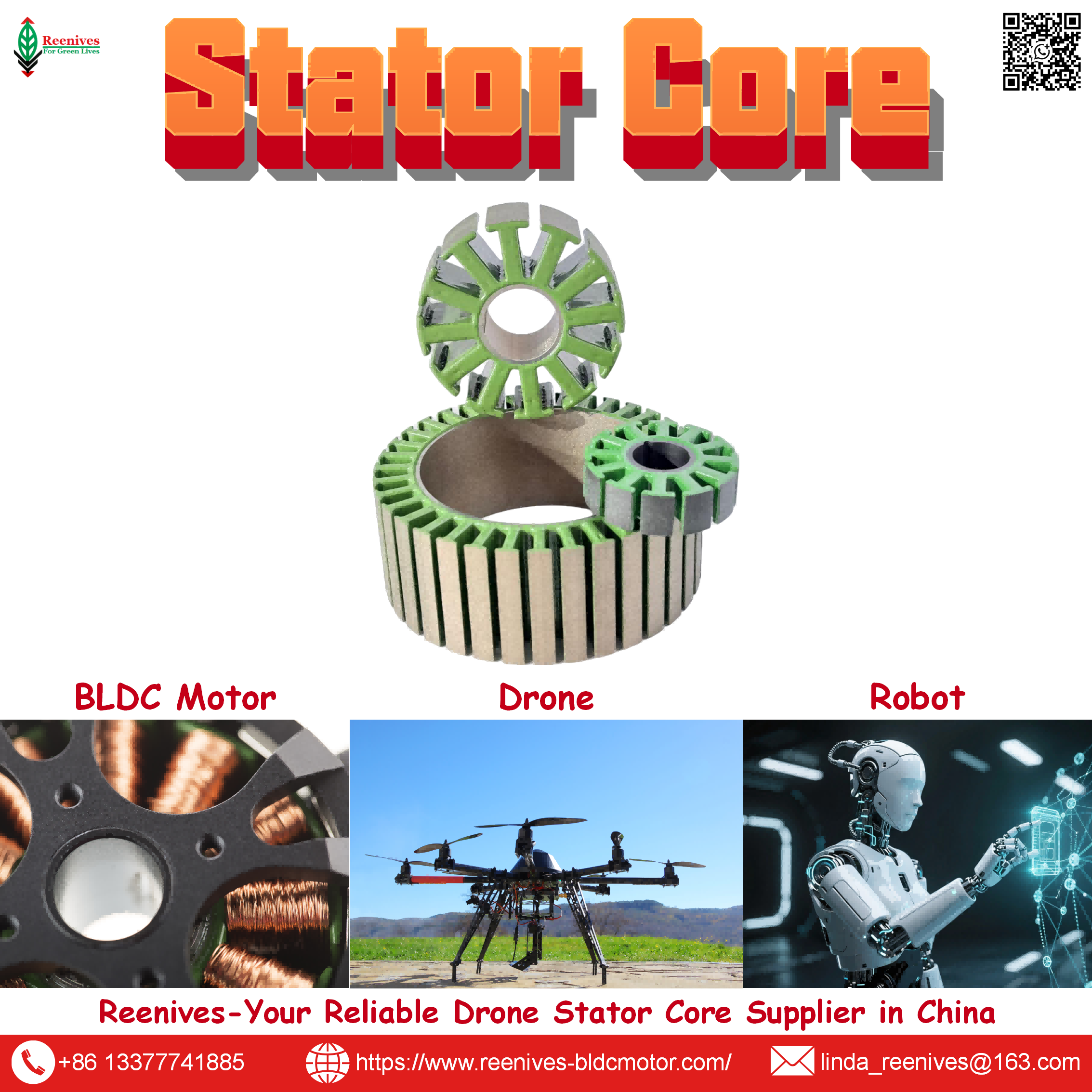
Classification of BLDC Drone Motor Stator Core

Classification of BLDC Drone Motor Stator Core: Six Axes That Turn a Category Into a Specification
A purchase order that says “0.20 mm stator core, 12 slots” has named two axes out of six — and left the other four to the supplier’s default. This is the quiet origin of most stator-related drone motor failures. Two cores can both be “0.20 mm, 12 slots” and still differ in slot geometry (slotted versus slotless), material (laminated steel versus SMC), stacking method (interlocked versus bonded), and concentricity tolerance — and those four differences determine whether the motor runs at ≤9.5 W/kg or drifts toward the 10–14 W/kg band, whether the winding process reaches 75% slot fill or stalls at 35%, and whether the air gap holds at 0.02 mm or wanders to 0.05 mm. The category label was correct. The specification was incomplete.
The published data shows how much sits inside the classification. A 0.35 mm lamination grade runs at roughly 28–35 W/kg at 1.0 T / 400 Hz; a 0.20 mm grade runs at roughly 10–14 W/kg, and Reenives publishes ≤9.5 W/kg for its drone grade, measured by Epstein frame per IEC 60404-2, with stacking factor ≥97% (epoxy bonded), B50 1.65–1.72 T, concentricity ≤0.02 mm, and burr height <0.03 mm. Switching from 0.35 mm to 0.20 mm reduces eddy-current loss by approximately 67% at the same flux density. And the slot-pole choice — 12N14P — delivers a winding factor of approximately 0.933 with very low cogging, which is why it dominates drone propulsion.
This guide defines the six axes that fully describe a BLDC drone stator core, separates the magnetic axes (core existence, slot geometry, lamination grade, slot-pole, material) from the dimensional axis, presents the published parameter set that makes each axis auditable, maps the classification to drone mission profiles, and closes with a five-step audit. Every figure below is traceable to a published specification or a named measurement standard.
In this guide — jump to the section your project needs:
- What Is a BLDC Drone Motor Stator Core? The Six-Axis Definition
- The Six Axes in Detail: Core, Slot, Grade, Slot-Pole, Material, Size
- Published Parameters per Axis: Core Loss, Winding Factor, Stacking Factor, Tolerance, and Material Trade-Offs
- Application Profiles: Which Axis Binds Which Drone Mission
- A 5-Step Stator Core Classification Audit
- FAQ: Axes, Core vs Coreless, Lamination Thickness, 12N14P, Materials, and Dimensional Tolerances
- Summary: Classify All Six Axes, Not Two
What Is a BLDC Drone Motor Stator Core? The Six-Axis Definition
A stator core is the stationary magnetic structure that carries the windings and provides a low-reluctance flux path between the rotor magnets and the stator coils. In a drone BLDC motor, it is the component that converts electrical current into magnetic flux, and the component that determines how much of that flux becomes torque rather than heat. “Stator core” is a category label; a classification requires six axes.
| Axis | Options | What It Changes | Visible in “0.20 mm, 12 slots”? |
|---|---|---|---|
| 1 · Core existence | Core type (radial) / Coreless (axial) | Flux path, iron loss, torque density, mass | No |
| 2 · Slot geometry | Slotted / Slotless | Cogging, torque density, inductance, speed ceiling | Partially (slot count, not geometry) |
| 3 · Lamination grade | 0.20 mm / 0.27 mm / 0.35 mm / 0.50 mm NO silicon steel | Core loss at frequency, thermal margin, cost | Yes (thickness), but not grade |
| 4 · Slot-pole combination | 9N12P / 12N14P / 18N24P / 24N28P | Winding factor, cogging profile, torque-ripple | Partially (slot count, not pole count) |
| 5 · Magnetic material | Laminated steel / SMC / Amorphous / PCB | Eddy-current behavior, saturation flux density, manufacturability | No |
| 6 · Dimensional envelope | OD, ID, stack height, tolerance, concentricity | Air-gap geometry, seating consistency, vibration | No |
Sources: Published BLDC stator classification (core type vs coreless; slotted vs slotless); published lamination comparison (0.20 mm vs 0.35 mm); 12N14P winding factor data; Reenives stator core specification (tolerance, concentricity, burr).
Procurement translation: a stator core specification that names only “0.20 mm, 12 slots” has classified two axes out of six. It has not named core existence, slot geometry, pole count, magnetic material, or dimensional tolerance. A supplier quoting to that specification is free to choose four axes on your behalf — and those four choices determine whether the motor’s thermal margin matches the design intent.
The Six Axes in Detail: Core, Slot, Grade, Slot-Pole, Material, Size
Axis 1 — Core existence: core type versus coreless
Published patent classification separates BLDC motors into a core type (radial) and a coreless type (axial) according to whether a stator core exists. In a core-type motor, the laminated steel stator carries the windings and provides a low-reluctance path; the magnetic circuit is symmetrical about the shaft, which produces low axial vibration noise and suits low-speed, high-torque operation. A coreless motor removes the steel entirely, eliminating iron loss and reducing mass, but removing the flux-concentrating path also reduces the torque the motor can produce for a given magnet field. For drone propulsion, the core type dominates because the flux concentration supports the torque requirement. Coreless designs appear where mass or iron loss is the binding constraint.
Axis 2 — Slot geometry: slotted versus slotless
| Geometry | Construction | Cogging | Torque Density | Drone Fit |
|---|---|---|---|---|
| Slotted | Teeth with slots; windings inserted into the slots | Present; reduced by slot-pole choice and skew | Highest | Mainstream FPV, UAV, heavy-lift — the default |
| Slotless | No teeth; windings placed in the air gap | Essentially eliminated | Lower — larger effective gap | High-speed applications where low inductance is an advantage; published as more expensive due to higher coil turns |
Source: Published BLDC slot geometry classification (slotted vs slotless; slotless produces high-speed motors with low inductance, more expensive due to more coil turns).
The slot geometry decision is a cogging-versus-torque-density trade. A slotted core concentrates flux at the teeth, which is why it delivers higher torque per unit volume, but the tooth-slot interaction produces cogging torque. A slotless core removes the teeth and the cogging, but the larger effective air gap lowers torque density and the winding requires more turns, which raises cost. For a drone motor that needs to hold a gimbal steady, the slotless classification may be worth the torque penalty; for a heavy-lift platform that needs maximum torque per unit mass, the slotted core remains the default.
Axis 3 — Lamination grade and thickness: the thermal-margin axis
Lamination thickness controls eddy-current loss, which scales with the square of both thickness and electrical frequency. Published comparison data separates the grades clearly.
| Thickness | Typical Grade | Iron Loss @ 1.0 T / 400 Hz | Best Fit | Relative Cost |
|---|---|---|---|---|
| 0.35 mm | 35W300 / 35W270 | ~28–35 W/kg | Industrial servo ≤3,000 RPM, low-speed torque motors | Low |
| 0.27 mm | 27W230 / 27W250 | ~18–24 W/kg | Mid-speed servo 3,000–8,000 RPM, robot joint actuators | Medium |
| 0.20 mm | 20W1200H / 20W1500H; Reenives drone grade | ~10–14 W/kg; Reenives ≤9.5 W/kg | High-speed ≥8,000 RPM, UAV, FPV, frameless motors | High |
Sources: Published lamination comparison (0.20 mm ~10–14 W/kg; 0.27 mm ~18–24 W/kg; 0.35 mm ~28–35 W/kg); Reenives specification (0.20 mm ≤9.5 W/kg @ 1.0 T / 400 Hz, Epstein frame, IEC 60404-2).
The motor-level consequence of the grade choice is thermal. A 60 W motor core with 0.35 mm laminations generating 8 W of iron loss at operating speed drops to approximately 2.5 W with 0.20 mm laminations — a 5.5 W saving that reduces steady-state winding temperature by an estimated 15–25°C and allows roughly 8–12% higher continuous torque before the thermal limit. Two stator cores that share the “0.20 mm” classification but differ in grade — one at ≤9.5 W/kg, one at 10–14 W/kg — will therefore produce motors with different thermal margins, even though the thickness label is identical.
Axis 4 — Slot-pole combination: the smoothness axis
The slot-pole combination defines the winding factor and the cogging profile. For drone propulsion, 12N14P is the dominant configuration because it achieves a fundamental winding factor of approximately 0.933 with very low cogging torque. The slots per pole per phase calculate to q = 12 ÷ (14 × 3) ≈ 0.286, making it a fractional-slot concentrated winding. The slight asymmetry between 12 slots and 14 poles means the magnets never align with all teeth simultaneously, which is why cogging is suppressed. 9N12P is used for high-speed applications where lower pole count reduces iron losses at the expense of slightly higher torque ripple. 18N24P and 24N28P appear on larger outrunners with different torque-ripple profiles.
Axis 5 — Magnetic material: laminated steel, SMC, amorphous, PCB
| Material | Advantage | Limitation | Drone Fit |
|---|---|---|---|
| Laminated silicon steel | Excellent magnetic properties within each sheet; cost-effective for radial-flux machines; dominant technology | Stacking factor reduces properties vs individual sheets; works best at lower frequency | Mainstream drone and FPV stator cores |
| Soft magnetic composite (SMC) | 3D net-shape compaction; particle-level insulation reduces eddy-current loss; suited to axial-flux cores | More expensive than steel sheets; lower saturation flux density requires a thicker stator; lower permeability limits torque | Axial-flux and high-frequency applications |
| Amorphous alloy | Very low core loss | Expensive and difficult to process | Specialised high-efficiency designs |
| PCB | Weight reduction up to 80%; no slot insulation; high repeatability; suited to high-speed medium-current uses | Lower current capacity than laminated designs; lower mechanical strength | High-speed drone and eVTOL applications where weight is binding |
Sources: Published SMC comparison (3D shape, high cost, lower saturation flux density, thicker stator); published PCB stator comparison (weight reduction up to 80%, lower current capacity, high-speed medium-current fit).
The material axis is not a quality ladder — it is a trade space. Laminated steel dominates drone propulsion because it offers the best combination of magnetic performance, manufacturability, and cost for radial-flux machines. SMC is specified where a 3D magnetic topology or high-frequency operation justifies its cost and its lower saturation flux density. PCB stators are specified where weight reduction is the binding constraint and the current requirement is moderate. A procurement comparison that treats these as interchangeable is comparing different physical regimes.
Axis 6 — Dimensional envelope and tolerances: the axis that sets the air gap
Published drone stator cores range from 16 mm to 120 mm outer diameter for drone-grade laminations, with stack heights from a few millimetres up to 80 mm for larger platforms. But the dimensional axis is not primarily about size — it is about tolerance. Reenives publishes critical tolerance ±0.05 mm, concentricity ≤0.02 mm, and burr height <0.03 mm on its drone stator cores. A 0.02 mm concentricity error on each side can be a meaningful fraction of a 0.10–0.12 mm FPV air gap, and a burr above 0.03 mm can pierce the interlamination coating during winding. The dimensional classification is therefore as consequential as the magnetic classification.
Published Parameters per Axis: Core Loss, Winding Factor, Stacking Factor, Tolerance, and Material Trade-Offs
| Axis | Auditable Parameter | Published Value / Range | Test Standard / Source |
|---|---|---|---|
| 1 · Core existence | Iron loss presence; torque density | Core type has iron loss; coreless eliminates it; coreless lower continuous torque | Published BLDC core vs coreless classification |
| 2 · Slot geometry | Cogging; inductance | Slotted: cogging present, higher torque density; slotless: cogging eliminated, higher speed via low inductance | Published slotted vs slotless comparison |
| 3 · Lamination grade | Core loss at 1.0 T / 400 Hz | 0.20 mm ≤9.5 W/kg; 0.27 mm 18–24 W/kg; 0.35 mm 28–35 W/kg | IEC 60404-2; Reenives specification; published comparison |
| 4 · Slot-pole | Winding factor; cogging | 12N14P ≈0.933, very low cogging; 9N12P lower pole count, higher speed bias | Published BLDC winding calculator |
| 5 · Material | Eddy-current behavior; saturation flux density; manufacturability | Laminated steel default; SMC 3D shape, lower Bsat, higher cost; PCB up to 80% weight reduction, lower current | Published SMC and PCB comparisons |
| 6 · Dimensional | Concentricity; tolerance; burr; stacking factor | Concentricity ≤0.02 mm; critical tolerance ±0.05 mm; burr <0.03 mm; stacking factor ≥97% (epoxy bonded) | Reenives specification |
Sources: Published BLDC classification and material comparisons; Reenives stator core specification (core loss, tolerance, concentricity, burr, stacking factor); published lamination comparison; 12N14P winding factor data.
The two-axis comparison trap: the most common procurement error is comparing two stator cores that match on Axis 3 (both “0.20 mm”) and Axis 4 (both “12 slots”) but differ on Axis 1, 2, 5, or 6. A 0.20 mm slotted laminated core at ≤9.5 W/kg is not the same product as a 0.20 mm slotless core with a different material and a looser concentricity band. The category label is identical. The classification is not. When a buyer compares them on unit price alone, the comparison is between two different thermal and mechanical regimes.
Application Profiles: Which Axis Binds Which Drone Mission
| Mission Class | Binding Axis | Why | Specification to Write |
|---|---|---|---|
| FPV racing / high-RPM | Axis 3 (lamination grade) | High electrical frequency amplifies eddy-current loss; thermal margin decides whether the motor holds thrust | 0.20 mm at ≤9.5 W/kg @ 1.0 T / 400 Hz; 12N14P; concentricity ≤0.02 mm |
| Cinematic / inspection | Axis 2 (slot geometry) and Axis 4 (slot-pole) | Vibration reaches the camera before it reaches the pilot; cogging and air-gap uniformity are visible | Slotted 12N14P with low cogging; concentricity ≤0.02 mm; slot geometry verified on sample |
| Agricultural spraying UAV | Axis 6 (dimensional tolerance) and Axis 3 (grade) | Continuous duty and harsh environment stress the coating and the air gap | Uniform epoxy coating; burr <0.03 mm; 0.20 mm grade; concentricity ≤0.02 mm |
| Heavy-lift / logistics | Axis 3 (stacking factor) and Axis 4 (slot-pole) | High continuous torque depends on flux density and a smooth torque profile | Stacking factor ≥97%; 18N24P or 24N28P; 0.20 mm at ≤9.5 W/kg |
| eVTOL / high-frequency | Axis 5 (material) and Axis 3 (grade) | High electrical frequency and weight constraints push SMC or PCB into consideration | Material trade study (laminated vs SMC vs PCB); 0.20 mm or thinner; thermal validation at operating frequency |
The pattern is that the binding axis shifts with the mission’s dominant physics. FPV racing binds on Axis 3 because the electrical frequency is high and iron loss becomes heat. Cinematic platforms bind on Axes 2 and 4 because cogging and air-gap uniformity are visible in the footage. Agricultural platforms bind on Axis 6 because the environment stresses the coating and the air gap. Heavy-lift binds on the stacking factor within Axis 3 and on the slot-pole within Axis 4 because continuous torque depends on flux density and smoothness. eVTOL pushes into Axis 5 because the frequency and weight constraints make material choice a first-order decision rather than a default.
A 5-Step Stator Core Classification Audit
- Fix the mission before the axes. State the propeller diameter, voltage platform, continuous duty cycle, and the binding constraint (thermal margin, vibration, weight, or cost). A 5-inch FPV and a 30-inch heavy-lift bind on different axes, and a classification audit that starts with the core rather than the mission will specify a core that fits a category but not a requirement.
- Name all six axes in the specification, not just thickness and slot count. Write the core existence (core type), slot geometry (slotted), lamination grade (0.20 mm at ≤9.5 W/kg @ 1.0 T / 400 Hz per IEC 60404-2), slot-pole (12N14P), material (laminated silicon steel), and dimensional envelope (concentricity ≤0.02 mm, critical tolerance ±0.05 mm, burr <0.03 mm, stacking factor ≥97%). A specification that names two axes leaves four to the supplier’s default.
- Require the core loss at the operating electrical frequency, not just at the datasheet test point. A grade that is adequate at 50 Hz may be marginal at 400 Hz, and the published comparison shows the difference between ≤9.5 W/kg and 28–35 W/kg at the same test point. Calculate the electrical frequency as RPM × pole pairs ÷ 60. For a 14-pole motor at 15,000 RPM, that is 1,750 Hz — well into the range where the 0.20 mm grade is the baseline rather than an upgrade.
- Audit the dimensional axis as part of the classification, not as a separate inspection. Require concentricity ≤0.02 mm, critical tolerance ±0.05 mm, and burr <0.03 mm on the finished core. Ask for the measurement method (vision or CMM for concentricity, optical comparator for burr). A core that passes the magnetic axes but fails the dimensional axis produces a motor that vibrates or shorts regardless of its core-loss grade.
- Compare only within the same classification coordinate, and ask for the evidence. Write the six axes for each quotation before comparing price. If the axes differ, the price difference is a classification difference, not a margin difference. Then ask for the finished-stack core-loss report, the stacking factor measurement, the concentricity record, and the burr data. A supplier who can produce those is classified with evidence; a supplier who cannot is classified by assertion.
FAQ: Axes, Core vs Coreless, Lamination Thickness, 12N14P, Materials, and Dimensional Tolerances
What are the main classification axes for a BLDC drone motor stator core?
Six independent axes define a BLDC drone stator core. Axis 1 is core existence: core type (radial) versus coreless (axial). Axis 2 is slot geometry: slotted versus slotless. Axis 3 is lamination grade and thickness: 0.20 mm, 0.27 mm, 0.35 mm, or 0.50 mm non-oriented silicon steel, each with a published core-loss band. Axis 4 is slot-pole combination: 9N12P, 12N14P, 18N24P, or 24N28P, which sets the winding factor and cogging profile. Axis 5 is magnetic material: laminated silicon steel, soft magnetic composite (SMC), amorphous alloy, or PCB. Axis 6 is the dimensional envelope: stator outer diameter, inner diameter, and stack height. A single stator sits at the intersection of one option from each axis. This is why “0.20 mm stator core” alone is not a specification — it names one axis out of six.
Source: Published BLDC stator classification (core vs coreless; slotted vs slotless); published lamination comparison; 12N14P data; Reenives dimensional specification.
What is the difference between a core-type and a coreless stator in a BLDC motor?
A core-type (radial) BLDC motor has a laminated steel stator core that carries the windings and provides a low-reluctance flux path. The magnetic circuit is symmetrical about the shaft, so axial vibration is low and the motor is suited to low-speed, high-torque operation. A coreless (axial) motor removes the steel core entirely and uses a non-magnetic winding support. Removing the core eliminates iron loss and reduces mass, but it also removes the flux-concentrating path, so torque density and continuous torque capacity fall. For drone propulsion, the core type dominates because the flux concentration supports the torque requirement. Coreless designs appear in high-speed, low-torque, or weight-critical applications.
Source: Published BLDC classification (core type vs coreless; symmetrical radial circuit, low axial vibration, suited to low-speed rotation).
How does lamination thickness affect drone stator core performance?
Lamination thickness controls eddy-current loss, which scales with the square of both thickness and electrical frequency. In a drone motor running at high electrical frequency, thick laminations generate significant eddy-current heat. Published comparison data places 0.35 mm grades at roughly 28–35 W/kg at 1.0 T / 400 Hz, and 0.20 mm grades at roughly 10–14 W/kg at the same test point. Reenives publishes its 0.20 mm drone grade at ≤9.5 W/kg at 1.0 T / 400 Hz, measured by Epstein frame per IEC 60404-2. Switching from 0.35 mm to 0.20 mm reduces eddy-current loss by approximately 67% at the same flux density, which becomes lower stator temperature and longer hover endurance.
Source: Published lamination comparison (0.20 mm ~10–14 W/kg; 0.35 mm ~28–35 W/kg; 67% eddy-current reduction); Reenives 0.20 mm specification (≤9.5 W/kg @ 1.0 T / 400 Hz, IEC 60404-2).
What slot-pole combination is used in BLDC drone stator cores, and what winding factor does it achieve?
12N14P (12 slots, 14 poles) is the dominant drone configuration because it achieves a fundamental winding factor of approximately 0.933 with very low cogging torque. The slots per pole per phase calculate to q = 12 ÷ (14 × 3) ≈ 0.286, making it a fractional-slot concentrated winding. Each coil wraps primarily around a single tooth, which shortens the end winding and reduces inactive copper. The slight slot-pole asymmetry means the magnets never align with all teeth simultaneously, which is why cogging is suppressed. 9N12P is used for lightweight, high-speed applications where lower pole count reduces iron losses at the expense of slightly higher torque ripple. 18N24P and 24N28P appear on larger outrunners with different torque-ripple profiles.
Source: Published BLDC winding calculator (12N14P: drones, multirotors, winding factor 0.933; 9N12P: high-speed, lower pole count reduces iron losses at the expense of slightly higher torque ripple).
What magnetic materials are used for drone stator cores, and how do they compare?
Four materials appear in drone stator cores. Laminated silicon steel is the dominant technology: it offers excellent magnetic properties within each sheet and is cost-effective for radial-flux machines. Soft magnetic composite (SMC) allows 3D net-shape compaction and reduces eddy-current loss at high frequency because of particle-level insulation, but it is more expensive than steel sheets and has lower saturation flux density, which requires a thicker stator. Amorphous alloy offers very low core loss but is expensive and difficult to process. PCB stators replace the steel core with a multilayer circuit board, cutting weight by up to 80% and enabling high-speed operation, but they handle less current than laminated designs. For drone propulsion, laminated silicon steel remains the default; SMC and PCB are specified for axial-flux or high-frequency applications where their trade-offs are acceptable.
Source: Published SMC comparison (3D shape, high cost, lower saturation flux density, thicker stator); published PCB comparison (weight reduction up to 80%, lower current capacity, high-speed medium-current fit).
What dimensional envelope and tolerances should a drone stator core hold?
Drone stator cores are typically small: published outer diameters range from 16 mm to 120 mm for drone-grade laminations, with stack heights from a few millimetres up to 80 mm for larger platforms. Critical dimensional tolerances are tight because the air gap is small. Reenives publishes critical tolerance ±0.05 mm and concentricity ≤0.02 mm on its drone stator cores, with burr height <0.03 mm. These are not cosmetic values: a 0.02 mm concentricity error on each side can be a meaningful fraction of a 0.10–0.12 mm FPV air gap, and a burr above 0.03 mm can pierce the interlamination coating during winding. The stator core’s dimensional classification is therefore as important as its magnetic classification.
Source: Reenives stator core dimensional specification (16–120 mm OD, ±0.05 mm critical tolerance, ≤0.02 mm concentricity, <0.03 mm burr).
Summary: Classify All Six Axes, Not Two
“Classification of BLDC drone motor stator core” is not a taxonomy exercise — it is the discipline that makes stator quotations comparable. A stator core is a coordinate in a six-dimensional space: core existence (core type vs coreless), slot geometry (slotted vs slotless), lamination grade (0.20 mm / 0.27 mm / 0.35 mm / 0.50 mm), slot-pole combination (9N12P / 12N14P / 18N24P / 24N28P), magnetic material (laminated steel / SMC / amorphous / PCB), and dimensional envelope (OD, ID, stack height, tolerance, concentricity). The part name on a drawing typically names lamination thickness and slot count — two axes — and leaves the other four to the supplier’s default.
The published parameters make each axis auditable. On Axis 3, the 0.20 mm grade runs at ≤9.5 W/kg at 1.0 T / 400 Hz per IEC 60404-2, the 0.27 mm grade at 18–24 W/kg, and the 0.35 mm grade at 28–35 W/kg, with the 0.35 → 0.20 mm switch reducing eddy-current loss by approximately 67%. On Axis 4, 12N14P delivers a winding factor of approximately 0.933 with very low cogging. On Axis 6, Reenives publishes concentricity ≤0.02 mm, critical tolerance ±0.05 mm, burr <0.03 mm, and stacking factor ≥97%. On Axis 5, laminated steel is the default; SMC, amorphous, and PCB are trade-offs with published cost and performance penalties.
The procurement takeaway is that a comparison across different classification coordinates is not a price comparison — it is a comparison of two different products. Write the six axes for each quotation before comparing the numbers, and if the axes do not match, the price difference is a classification difference rather than a margin difference. That discipline eliminates the most expensive error in stator sourcing: paying for a specification you did not actually receive.
Classifying a stator core for a BLDC drone programme?
Reenives publishes the full Axis 3 and Axis 6 specification your audit needs: 0.20 mm silicon steel, core loss ≤9.5 W/kg at 1.0 T / 400 Hz per IEC 60404-2, B50 1.65–1.72 T, stacking factor ≥97% (epoxy bonded), concentricity ≤0.02 mm, critical tolerance ±0.05 mm, and burr height <0.03 mm, in 9N12P, 12N14P, 18N24P, and 24N28P configurations. Finished-stack reports, matched stator-rotor pairs, private mould development, and free samples are available for qualified engineering evaluations.
WhatsApp: +86-13377741885
Email: linda_reenives@163.com
Official website: www.reenives-bldcmotor.com
Dongguan Runlu Motor Technology Co., Ltd.
Reenives — Drone Motor One-Stop Solution Supplier
Reenives is a professional drone stator core manufacturer, founded in 2022. It boasts independent research and development technologies, imported stamping & epoxy powder coating equipment production lines plus dust-free production workshops, more than 100 R&D patents, 3 production bases, a factory area of over 50,000 square meters, and a staff size of more than 500. From production to sales, we support bulk purchasing, private mould development, and sample making, and can provide tailor-made perfect solutions for your production and usage scenarios. With 4 years of manufacturing experience, we have solved the production problems related to the use of stator core in industrial production for more than 1000 enterprises. We can ship globally (with complete export qualifications). Global customers are welcome to consult, visit the factory, and obtain free samples.
0.20 mm silicon steelCore loss ≤9.5 W/kg @ 1.0 T / 400 HzB50 1.65–1.72 TStacking factor ≥97%Concentricity ≤0.02 mmBurr <0.03 mm9N12P · 12N14P · 18N24P · 24N28PGlobal export qualifications
Parameters of Drone Motor Stator Core
Classification of Drone Motor
Related Article