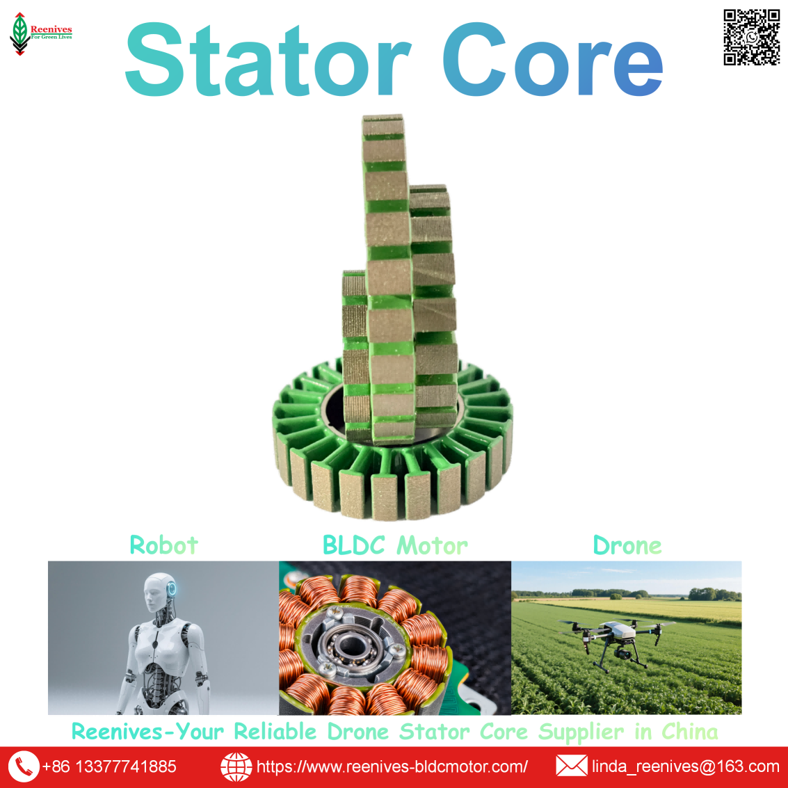
Processing of Radial Flux Motor

Processing of Radial Flux Motor: Six Stages, Published Tolerances, and the Audit That Separates a Production Line from a Prototype Bench
A radial flux motor that spins on a prototype bench and a radial flux motor that holds its thrust curve for a full season are the same design and a different process chain. The design determines the geometry. The process determines whether the geometry survives. Published drone motor assembly guidance decomposes that process into three macro steps — stator pre-treatment and assembly, rotor pre-treatment and assembly, and stator-rotor mating plus testing — and each macro step contains controls that decide whether the air gap stays uniform, the insulation survives, and the rotor stays balanced. The failure modes are not random. They are the predictable output of a process chain that missed a tolerance at a specific stage.
The published tolerances are concrete. Winding holds wire tension fluctuations within ±0.05 N and wire placement accuracy better than ±0.03 mm, with tooling aligned to ±0.02 mm. Stator-rotor mating holds alignment error ≤0.05 mm and mating force within ±5% of design — for example 1,000 N ± 50 N — to avoid air-gap distortion. Rotor balancing runs above 10,000 RPM to G2.5 grade with residual unbalance around 3 mg, and 100% no-load testing screens KV and current before shipment. These are not machine specifications. They are process control points — and a supplier who cannot state them has described a capability, not a production line.
This guide walks the processing of a radial flux motor stage by stage, with the published tolerance at each stage, the failure mode it prevents, and the audit question a procurement engineer should ask. It is written for the engineer who has to qualify a supplier’s process chain, not just compare a datasheet.
In this guide — jump to the section your project needs:
- What Is the Processing of a Radial Flux Motor? The Six-Stage Chain Defined
- Process Route Classification: Flyer vs Needle Winding, Interlock vs Weld vs Bond Stacking, Concentrated vs Distributed Winding
- Published Tolerances by Stage: Stamping, Stacking, Winding, Rotor Assembly, Mating, and End-of-Line Test
- Application Profiles: How the Process Chain Changes for Drone, UAV, and FPV Missions
- A 5-Step Radial Flux Motor Process Audit for Procurement Engineers
- FAQ: Stage List, Stamping Tolerances, Winding Accuracy, Air-Gap Control, EOL Tests, Core Parameters, and Chain Qualification
- Summary: Qualify the Chain, Not the Machine
What Is the Processing of a Radial Flux Motor? The Six-Stage Chain Defined
The processing of a radial flux motor is the sequence of manufacturing operations that converts silicon steel, copper wire, permanent magnets, and structural components into a tested motor. Published drone motor assembly guidance decomposes it into three macro steps — stator pre-treatment and assembly, rotor pre-treatment and assembly, and stator-rotor mating plus testing — which expand into six controlled stages when the internal process controls are made explicit.
| Stage | Core Operation | Primary Control Point | Published Tolerance / Method |
|---|---|---|---|
| 1 · Stamping | Progressive die punching of stator and rotor laminations from silicon steel | Burr height, slot geometry, outer diameter | Burr <0.03 mm by optical comparator; embossing depth below 80–90% of sheet thickness for interlock joints |
| 2 · Stacking | Interlocking, laser welding, or adhesive bonding to a specified stack height | Stacking factor, stack height, interlamination integrity | Stacking factor ≥97% by weight/dimension; hydraulic press to eliminate stacking gaps |
| 3 · Winding | Enameled wire placed into stator slots under controlled tension | Tension, wire placement accuracy, insulation integrity | Tension ±0.05 N; placement ±0.03 mm; tooling alignment ±0.02 mm; flyer 2,000–5,000 rpm |
| 4 · Rotor assembly | Shaft turning, magnet installation with epoxy, curing, dynamic balancing | Shaft tolerance, magnet position and adhesion, balance grade | Shaft key dimension tolerance ~±0.005 mm; balance G2.5 at >10,000 rpm, ~3 mg unbalance |
| 5 · Stator-rotor mating | Servo-driven mating with encoder feedback and force control | Alignment error, mating force, air-gap uniformity | Alignment ≤0.05 mm; force within ±5% (e.g., 1,000 N ± 50 N); missing-part detection after mating |
| 6 · End-of-line test | Electrical, mechanical, and no-load performance verification | Insulation integrity, KV, current, balancing | 100% Hi-Pot, surge, resistance/inductance, no-load; KV and no-load current screening |
Sources: Published drone motor assembly guidance (stator pre-treatment, rotor pre-treatment, mating and testing; stacking press; shaft tolerance; mating alignment and force); BLDC stator winding process data (tension, placement, tooling alignment, flyer speed); drone motor testing platform data (balancing, no-load screening, Hi-Pot, surge); published interlocking process analysis (embossing depth limit).
Procurement translation: the processing chain is the product specification. A supplier who quotes a stator core drawing and a winding pattern has described the design. A supplier who can state the burr limit at stamping, the stacking factor at stacking, the tension window at winding, the balance grade at rotor assembly, the alignment tolerance at mating, and the test coverage at end-of-line has described a production process. The first supplier is selling a design; the second is selling a motor that will meet it.
Process Route Classification: Flyer vs Needle Winding, Interlock vs Weld vs Bond Stacking, Concentrated vs Distributed Winding
Winding architecture: flyer versus needle
| Architecture | Mechanism | Slot Orientation | Drone Relevance |
|---|---|---|---|
| External flyer winding | High-speed rotating flyer guides wire around stator teeth; 2,000–5,000 rpm | Outward-facing slots | Standard for drone and RC outrunner stators; high productivity for volume |
| Internal needle winding | Servo-driven needle reciprocates vertically; tooling indexes horizontally for layer-by-layer placement | Inward-facing slots | Power tools, pumps, EV traction, servo motors; not the default for drone outrunners |
Source: Published BLDC stator winding process guide (flyer for outer-rotor outward-facing slots at 2,000–5,000 rpm; needle for inner-rotor inward-facing slots).
Stacking method: interlock, weld, or bond
| Method | Mechanism | Advantage | Constraint |
|---|---|---|---|
| Interlocking (self-clinching) | Embossed tabs on each lamination lock into the adjacent sheet | Most economical for volume production; no consumables | Embossing depth is decisive; above 80–90% of sheet thickness, joint failure risk rises |
| Laser welding / mechanical interlock on OD | Welded or mechanically locked at the outer diameter after stacking | Higher joint strength; suitable for larger stacks | Heat-affected zone; weld spatter risk; coating damage at weld seam |
| Adhesive bonding | Bonded laminations with epoxy or varnish | Highest stacking factor; no interlock tabs to distort the magnetic path | Process control for bond coverage and cure; slower cycle time |
Sources: Published interlocking process analysis (embossing depth limit; joint failure risk); published stator stacking guidance (interlocking, welding, bonding at OD); drone motor assembly guidance (hydraulic press to eliminate stacking gaps; vacuum impregnation after winding).
Winding configuration: concentrated versus distributed
Published BLDC stator winding guidance distinguishes concentrated winding — each coil wound around a single tooth, producing short end turns and reduced copper loss — from distributed winding, where each coil spans multiple slots and produces a more sinusoidal back-EMF. Concentrated winding is the standard for fractional-slot concentrated winding (FSCW) motors, and published guidance explicitly lists drone propulsion motors among its typical applications. Distributed winding is used in high-speed, low-noise, low-vibration applications such as blower motors and EV traction. For a drone radial flux motor, the concentrated configuration is the default because it shortens end turns and reduces the copper mass that adds weight without contributing to torque.
Published Tolerances by Stage: Stamping, Stacking, Winding, Rotor Assembly, Mating, and End-of-Line Test
Stamping and stacking — the magnetic foundation
Stamping controls burr height and slot geometry; stacking controls stacking factor and stack height. Published interlocking process analysis identifies embossing depth as the decisive parameter for the interlock joint, and states that above an embossing depth of 80–90% of the sheet thickness, the risk of joint failure increases. Reenives publishes burr height <0.03 mm by optical comparator and stacking factor ≥97% by the weight/dimension method on its radial flux drone stator cores. Published drone motor assembly guidance adds that after stacking, a hydraulic press applies pressure to eliminate stacking gaps, with laser measurement monitoring stack height in real time. The failure modes are direct: a burr that pierces the interlamination coating creates a local short that becomes a hot spot; a loose stack wastes the flux density the steel grade was selected to provide.
Winding — the insulation gate
Published BLDC stator winding process data specifies wire tension fluctuations within ±0.05 N, wire placement accuracy better than ±0.03 mm, and tooling, wire guide plates, and winding needle alignment to ±0.02 mm. The purpose is stated directly: these controls prevent common winding defects such as wire crossover, skipped turns, and enamel insulation damage. For drone outrunners, the external flyer architecture runs at 2,000–5,000 rpm and is the standard for outward-facing slots. After winding, published assembly guidance includes vacuum impregnation to enhance insulation performance before the stator is inserted into the housing with a self-centering fixture that ensures concentricity.
Rotor assembly — balance and magnet integrity
Published drone motor assembly guidance specifies rotor shaft machining to a key dimension tolerance of approximately ±0.005 mm, followed by magnet installation with epoxy dispensing and curing to a specified tensile strength. Dynamic balancing is then performed on a machine supporting speeds above 10,000 RPM and achieving G2.5 grade, with unbalance data around 3 mg. The rotor assembly stage is where the balance state is created; the mating stage cannot correct an unbalanced rotor, and the end-of-line test can only reject it.
Stator-rotor mating — the air-gap gate
Published assembly guidance describes the mating mechanism as servo-driven with a high-precision encoder monitoring rotor position in real time, holding alignment error ≤0.05 mm, and applying mating force within ±5% of the design value — for example 1,000 N ± 50 N — to avoid air-gap distortion from over- or under-press. After mating, sensors verify that no magnets or coils are missing before electrical testing. The air gap itself is the product of the whole tolerance chain: stator bore concentricity, rotor outer diameter runout, bearing seat position, and mating alignment all contribute, which is why air-gap uniformity cannot be inspected on a single part.
End-of-line test — the evidence gate
Published drone motor testing platforms perform 100% no-load testing before shipment, monitoring KV value and no-load current, and screen every motor against qualified performance before delivery. The electrical test set includes Hi-Pot testing, resistance and inductance testing, and surge waveform testing. Broader end-of-line frameworks repeat insulation testing — insulation resistance, Hi-Pot, surge, or partial discharge — at the final stage specifically to verify that assembly operations did not damage the insulation, and typically introduce a short no-load test cycle for 100% quality control at the end of the line. Rotor balancing and shaft accuracy are checked because runout affects balance. The coverage question is decisive: 100% testing catches the individual unit that will fail in flight; sampled testing confirms only the process average.
| Stage | Published Parameter | Test / Control Method | Failure Mode If Missed |
|---|---|---|---|
| Stamping | Burr <0.03 mm; embossing depth below 80–90% of sheet thickness | Optical comparator; interlock joint strength test | Coating piercing → interlaminar short → hot spot |
| Stacking | Stacking factor ≥97%; stack height controlled | Weight/dimension; hydraulic press with laser height monitoring | Loose stack → lost flux density → higher current for same torque |
| Winding | Tension ±0.05 N; placement ±0.03 mm; tooling ±0.02 mm | Closed-loop tensioner; servo axis with encoder | Enamel damage → turn-to-turn short; crossover → fill loss |
| Rotor | Shaft ~±0.005 mm; balance G2.5 at >10,000 rpm, ~3 mg | CNC turning/grinding; dynamic balancing machine | Vibration; bearing wear; NVH |
| Mating | Alignment ≤0.05 mm; force ±5% (1,000 N ± 50 N) | Servo + encoder; pressure control; missing-part sensors | Air-gap distortion → rub, torque ripple, noise |
| EOL | 100% Hi-Pot, surge, R/L, no-load; KV and current screen | Automated test station | Latent short escapes; KV drift reaches the field |
Sources: Published interlocking process analysis (embossing depth, joint failure); drone motor assembly guidance (stacking press, shaft tolerance, mating alignment and force, vacuum impregnation); BLDC stator winding process data (tension, placement, tooling, flyer speed); drone motor testing platform data (balancing grade, no-load, Hi-Pot, surge); published EOL testing framework (repeat insulation test, 100% no-load QC).
The chain-propagation trap: a stamping burr becomes a stacking short; a stacking gap becomes a flux-density loss; a winding tension drift becomes an insulation defect; a mating misalignment becomes air-gap vibration. Each stage’s output is the next stage’s input, and the end-of-line test is the only place where the accumulated effect becomes visible. A supplier who can show a passing end-of-line record but cannot trace the parameter back through stamping, stacking, winding, and mating has shown a test result, not a controlled process. The audit question is not “did the unit pass?” — it is “which stage controlled the parameter that made it pass, and can you show that control record?”
Application Profiles: How the Process Chain Changes for Drone, UAV, and FPV Missions
| Mission Class | Process Emphasis | Binding Stage | Why |
|---|---|---|---|
| FPV racing / high-RPM | Winding tension and rotor balance | Stages 3 and 4 | Fine wire at high electrical frequency exposes enamel damage and unbalance immediately; a single tension excursion becomes a short under thermal load |
| Cinematic / inspection FPV | Mating alignment and concentricity | Stage 5 | Air-gap uniformity governs vibration, and vibration reaches the camera before it reaches the pilot |
| Agricultural spraying UAV | Vacuum impregnation and coating integrity | Stages 3 and 6 | Long, wet, thermal duty cycle stresses the insulation barrier; impregnation and coating are the survival layer |
| Heavy-lift / logistics UAV | Stacking factor and mating force | Stages 2 and 5 | Continuous torque depends on flux density from a tight stack and a uniform air gap from controlled mating force |
| Multi-model production | Changeover discipline and first-off inspection | All stages | A model switch re-baselines every stage; first-off inspection after changeover is the only control that catches a mis-seated fixture or a wrong recipe |
The pattern is that the binding stage tracks the mission’s dominant failure mechanism. FPV and high-speed platforms bind on winding and rotor balance because fine wire and high RPM expose insulation and unbalance first. Cinematic and inspection platforms bind on mating alignment because vibration is the visible failure. Agricultural platforms bind on impregnation and coating because the environment attacks the insulation barrier. Heavy-lift platforms bind on stacking factor and mating force because continuous torque depends on flux density and gap uniformity. Multi-model production binds on the entire chain because the process, not the design, is what changes between runs.
A 5-Step Radial Flux Motor Process Audit for Procurement Engineers
- Ask for the stage-by-stage control plan, not a capability statement. Request the control point at each of the six stages: burr and embossing depth at stamping, stacking factor and stack height at stacking, tension and placement accuracy at winding, shaft tolerance and balance grade at rotor assembly, alignment and force at mating, and test coverage at end-of-line. A supplier who can map all six is describing a production chain. A supplier who names only the winding machine and the test bench has described two stages out of six.
- Verify the winding control points with numbers, not adjectives. Write tension fluctuation within ±0.05 N, wire placement accuracy better than ±0.03 mm, and tooling alignment within ±0.02 mm into the process specification. Ask for the tension controller resolution and the servo axis positioning data. Ask whether the winding is concentrated or distributed, and confirm that the flyer architecture matches the stator’s slot orientation — external flyer for outward-facing drone outrunner slots, internal needle for inward-facing slots.
- Audit the mating stage as the air-gap gate. Ask for the alignment error specification (published guidance: ≤0.05 mm), the mating force control (±5%, e.g., 1,000 N ± 50 N), and the encoder feedback method used to hold rotor position during mating. A supplier who cannot describe the mating control has not addressed the stage where the air gap — the dimension that decides vibration and torque ripple — is physically set.
- Require 100% end-of-line coverage and review the test item list. Specify Hi-Pot, surge waveform, resistance/inductance, and no-load (KV and current) testing on every unit, plus rotor balancing verification at G2.5 or better. Ask for a recent record showing a unit that failed surge testing and was rejected. A supplier with no rejected units is either perfect or not testing; the rejected unit is the evidence that the inspection process is real.
- Trace one parameter through the chain before committing to volume. Pick the air gap and trace it back: stator bore concentricity (purchased core) → stacking factor (stacking stage) → mating alignment and force (mating stage) → no-load vibration and noise (end-of-line test). If the supplier can show the control record at each link, the chain is qualified. If any link is missing, the air-gap outcome is being assumed rather than controlled. For the stator core baseline, Reenives publishes 0.20 mm silicon steel, core loss ≤9.5 W/kg at 1.0 T / 400 Hz per IEC 60404-2, B50 1.65–1.72 T, stacking factor ≥97%, concentricity ≤0.02 mm, critical tolerance ±0.05 mm, burr <0.03 mm, and C5 epoxy coating at >1400 V per ASTM D149 — the same value-plus-standard-plus-location discipline applies to every stage of the processing chain.
FAQ: Stage List, Stamping Tolerances, Winding Accuracy, Air-Gap Control, EOL Tests, Core Parameters, and Chain Qualification
What are the main stages in the processing of a radial flux motor?
Radial flux motor processing runs through six controlled stages: (1) lamination stamping, where silicon steel sheet is punched into the stator and rotor profiles; (2) stacking, where laminations are interlocked, welded, or bonded to a specified stack height; (3) winding, where enameled wire is placed into the stator slots under controlled tension; (4) rotor assembly, where magnets are installed, bonded, cured, and the rotor is dynamically balanced; (5) stator-rotor mating, where the air gap is set under controlled force and alignment; and (6) end-of-line testing, where 100% of motors receive Hi-Pot, surge waveform, resistance, no-load, and balancing verification. Each stage has a published tolerance, and a defect at any stage propagates forward — which is why the process chain, not the individual machine, is the unit of qualification.
Source: Published drone motor assembly guidance (stator pre-treatment, rotor pre-treatment, mating and testing); BLDC stator winding process data; drone motor testing platform data.
What stamping and stacking tolerances matter in radial flux motor processing?
Stamping controls burr height and slot geometry; stacking controls stacking factor and stack height. Published processing guidance for interlocking specifies that embossing depth is the decisive parameter, and that above an embossing depth of 80–90% of sheet thickness the risk of joint failure increases. Reenives specifies burr height <0.03 mm by optical comparator and stacking factor ≥97% by the weight/dimension method on its radial flux drone stator cores. A burr that pierces the interlamination coating creates a local short that becomes a hot spot; a loose stack wastes the flux density the steel grade was selected to provide. Both must be measured on the finished stack, not inferred from the material certificate.
Source: Published interlocking process analysis (embossing depth limit; joint failure risk); Reenives stator core specification (burr <0.03 mm, stacking factor ≥97%); published assembly guidance (hydraulic press to eliminate stacking gaps).
What tension and wire placement accuracy should radial flux motor winding hold?
Published BLDC stator winding process data specifies wire tension fluctuations within ±0.05 N and wire placement accuracy better than ±0.03 mm, with tooling, wire guide plates, and winding needles aligned to a positioning accuracy of ±0.02 mm. These values are not preferences — they are the parameters that prevent wire crossover, skipped turns, and enamel insulation damage. For drone radial flux outrunners, external flyer winding is the standard architecture for outward-facing slots, running at 2,000–5,000 rpm. Concentrated winding is the drone default because it shortens end turns and reduces copper loss, while distributed winding is reserved for high-speed low-noise applications where sinusoidal back-EMF matters more than compactness.
Source: Published BLDC stator winding process guide (tension ±0.05 N, placement ±0.03 mm, tooling ±0.02 mm, flyer 2,000–5,000 rpm, concentrated vs distributed).
How is the air gap controlled during stator-rotor mating in radial flux motor processing?
Published drone motor assembly guidance specifies that the mating mechanism is driven by a servo motor with a high-precision encoder monitoring rotor position in real time, holding alignment error to ≤0.05 mm. The mating force is controlled by pneumatic or hydraulic pressure within ±5% of the design value — for example 1,000 N ± 50 N — to avoid air-gap distortion from over- or under-press. After mating, sensors verify that no magnets or coils are missing before electrical testing. The air gap itself is the product of the whole tolerance chain: stator bore concentricity, rotor outer diameter runout, bearing seat position, and mating alignment all contribute, which is why air-gap uniformity cannot be inspected on a single part.
Source: Published drone motor assembly guidance (servo-driven mating, alignment ≤0.05 mm, force ±5%, missing-part detection); published rotor assembly tolerance guidance (air gap as result of whole tolerance chain).
What end-of-line tests does radial flux motor processing require?
Published drone motor testing platforms perform 100% no-load testing before shipment, monitoring KV value and no-load current, and screen every motor against qualified performance before delivery. The electrical test set includes Hi-Pot testing, resistance and inductance testing, and surge waveform testing. Shaft accuracy is monitored after rotor pressing because runout affects balancing, and rotor balancing is performed on a machine supporting speeds above 10,000 RPM and achieving G2.5 grade, with unbalance data around 3 mg. Broader end-of-line frameworks add dynamic BEMF, three-phase short-circuit, cogging/torque ripple, and NVH evaluation. The coverage question is decisive: 100% testing catches the individual unit that will fail in flight; sampled testing confirms only the process average.
Source: Drone motor testing platform data (100% no-load, KV/current screen, Hi-Pot, surge, balancing G2.5, ~3 mg); published EOL testing framework (repeat insulation test, 100% no-load QC, BEMF, three-phase short, cogging/torque ripple).
What stator core parameters should be specified when qualifying a radial flux motor process?
The process qualification must reference the stator core parameters that the process is designed to deliver. Reenives publishes radial flux drone stator cores at 0.20 mm non-oriented silicon steel, core loss ≤9.5 W/kg at 1.0 T / 400 Hz per IEC 60404-2 on the finished stack, B50 1.65–1.72 T, stacking factor ≥97%, concentricity ≤0.02 mm by vision measurement, critical tolerance ±0.05 mm, burr height <0.03 mm by optical comparator, and C5 epoxy coating at >1400 V per ASTM D149 across −40°C to 180°C, in 12N14P and related slot-pole configurations. Each parameter is expressed as value plus standard plus measurement location, so it can be audited on the finished part rather than read from a mill certificate.
Source: Reenives radial flux stator core specification (core loss, B50, stacking factor, concentricity, tolerance, burr, coating, slot-pole); IEC 60404-2; ASTM D149.
Why does a radial flux motor process need to be qualified as a chain rather than as individual machines?
Because the tolerances compound. A stamping process with uncontrolled burr produces a stack that has already failed at the stacking stage, regardless of how good the stacking machine is. A winding process with tension drift produces a stator whose insulation is already compromised before the mating stage, regardless of how precise the mating press is. An air-gap alignment error at mating produces vibration that the balancing machine cannot fully correct, because the unbalance source is the gap itself, not the rotor mass distribution. Each stage’s output is the next stage’s input, and the final end-of-line test is the only place where the accumulated effect becomes visible. That is why the audit should trace a parameter from stamping through to the test record, not check each machine in isolation.
Source: Published drone motor assembly guidance (three macro steps with compounding tolerances); published winding and mating control data.
Summary: Qualify the Chain, Not the Machine
The processing of a radial flux motor is a six-stage chain — stamping, stacking, winding, rotor assembly, stator-rotor mating, and end-of-line test — and each stage carries a published tolerance that determines whether the motor holds its thrust curve or fails in the field. The winding stage holds tension within ±0.05 N and placement within ±0.03 mm. The mating stage holds alignment ≤0.05 mm and force within ±5%. The rotor stage holds G2.5 balance at >10,000 RPM with ~3 mg residual unbalance. And the end-of-line stage performs 100% Hi-Pot, surge, and no-load testing with KV and current screening.
The procurement takeaway is that the chain, not the machine, is the unit of qualification. A supplier who can state the burr limit at stamping, the stacking factor at stacking, the tension window at winding, the balance grade at rotor assembly, the alignment tolerance at mating, and the test coverage at end-of-line is describing a production process. A supplier who quotes only a winding machine and a test bench has described two stages out of six, and the other four stages are where the field failures originate. For a drone programme where a turn-to-turn short or an air-gap eccentricity becomes an in-flight failure, that distinction is the whole procurement decision.
Qualifying a radial flux motor process for a drone propulsion programme?
Reenives publishes the stator core parameter discipline that the processing chain is designed to deliver: 0.20 mm non-oriented silicon steel, core loss ≤9.5 W/kg at 1.0 T / 400 Hz per IEC 60404-2, B50 1.65–1.72 T, stacking factor ≥97%, concentricity ≤0.02 mm, critical tolerance ±0.05 mm, burr height <0.03 mm, and C5 epoxy coating at >1400 V per ASTM D149, in 12N14P and related slot-pole configurations. Finished-stack reports, matched stator-rotor pairs, private mould development, and free samples are available for qualified engineering evaluations.
WhatsApp: +86-13377741885
Email: linda_reenives@163.com
Official website: www.reenives-bldcmotor.com
Dongguan Runlu Motor Technology Co., Ltd.
Reenives — Drone Motor One-Stop Solution Supplier
Reenives is a professional drone stator core manufacturer, founded in 2022. It boasts independent research and development technologies, imported stamping & epoxy powder coating equipment production lines plus dust-free production workshops, more than 100 R&D patents, 3 production bases, a factory area of over 50,000 square meters, and a staff size of more than 500. From production to sales, we support bulk purchasing, private mould development, and sample making, and can provide tailor-made perfect solutions for your production and usage scenarios. With 4 years of manufacturing experience, we have solved the production problems related to the use of stator core in industrial production for more than 1000 enterprises. We can ship globally (with complete export qualifications). Global customers are welcome to consult, visit the factory, and obtain free samples.
0.20 mm silicon steelCore loss ≤9.5 W/kg @ 1.0 T / 400 HzStacking factor ≥97%Concentricity ≤0.02 mmBurr <0.03 mmC5 epoxy >1400 V12N14P · 9N12P · 18N24P · 24N28PGlobal export qualifications
What is Radial Flux Electric Motor?
Related Article