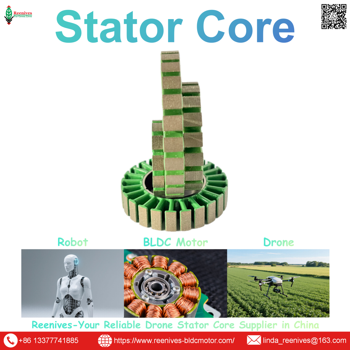
Advantage of Axial Flux Stator

Advantage of Axial Flux Stator: Geometry, SMC Core Performance, and the Drone Propulsion Trade-Off
The advantage of an axial flux stator is not incremental. It is a different scaling law. In a radial flux motor, the active magnetic flux area is the cylindrical surface of the stator bore — it scales as diameter × length (D·L), a linear relationship. In an axial flux motor, the flux area is the annular disc face — it scales with the square of diameter (D²). Published comparison data states the consequence directly: axial flux delivers a power-to-weight ratio that is 2–5× that of radial flux, with excellent torque density at low RPM and a very short axial length. Double the diameter of a radial motor and the flux area doubles. Double the diameter of an axial motor and the flux area quadruples. That is why published SAE analysis for UAV propulsion concludes that the axial flux permanent magnet motor boasts higher speed, power density, lower weight, and greater efficiency than the radial flux equivalent, because of its shorter flux path and the absence of end-turn winding.
But the same geometry that delivers the advantage also creates the production constraint. Published design guidance is direct: uneven air gap is one of the most prevalent issues in axial flux core design, axial flux motors often require tighter axial-direction tolerances than radial flux because dual air gaps make tolerance stack-up harder to control, and the stator carrier, rotor disc, core segments, and housing must be processed with strict flatness and parallelism control. The advantage is real. Whether it reaches the field depends on whether the stator supplier can hold that tolerance. This guide separates the geometric advantage from the manufacturing burden, so that a procurement decision can be made on both.
In this guide — jump to the section your project needs:
- What Is an Axial Flux Stator? The Geometry, the Definition, and the Scaling Law
- Axial Flux Stator Configurations: Yokeless Torus, Back-Iron Disc, Coreless, and the SMC-versus-Lamination Route
- Published Parameters and Advantages: Power Density, Torque Density, Core Loss at Frequency, Flatness, and Air-Gap Tolerance
- Application Profiles: Which Drone Mission Binds the Axial Flux Advantage
- A 5-Step Axial Flux Stator Selection Workflow for Drone Propulsion
- FAQ: Geometric Advantage, Radial Comparison, Core Material, Air-Gap Tolerance, Configurations, and Mission Fit
- Summary: The Advantage Is Real — the Tolerance Is the Gate
What Is an Axial Flux Stator? The Geometry, the Definition, and the Scaling Law
An axial flux stator is the stationary magnetic component of an axial flux machine — a disc-shaped core that carries the windings and guides magnetic flux parallel to the rotation axis, rather than radially across a cylindrical bore. Published Reenives design guidance describes it as the defining heart of the topology: unlike the cylindrical cores of common radial flux motors, axial flux cores are disc-shaped with flux flowing parallel to the motor’s axis of rotation, and the compact “pancake” geometry enables shorter, more efficient magnetic flux paths and allows multi-rotor, single-stator arrangements.
The advantage follows from the scaling law. Published comparison analysis explains that in a radial flux motor the effective magnetic flux area is the surface area of the active cylinder, which scales as diameter × length — a linear relationship — while in an axial flux motor the flux area is the annular disc surface, which scales with the square of diameter. Doubling the diameter of a radial motor doubles its flux area; doubling the diameter of an axial motor quadruples it. That is why axial flux motors achieve higher power density as size increases, and why the advantage grows more decisive in the 1 kW and above range.
Procurement translation: the advantage of an axial flux stator is a geometric property, not a supplier claim. But the geometry that produces the D² scaling also produces the dual-air-gap tolerance requirement. A supplier who quotes the power-density advantage without stating the core construction route (SMC or lamination), the flatness and parallelism tolerance, and the air-gap control method has quoted the geometry and left the manufacturing burden to the buyer.
Axial Flux Stator Configurations: Yokeless Torus, Back-Iron Disc, Coreless, and the SMC-versus-Lamination Route
Stator core configurations
| Configuration | Construction | Advantage | Constraint | Drone / UAV Fit |
|---|---|---|---|---|
| Yokeless (Torus) | Individual laminated teeth arranged in a ring, no back-iron | Significantly reduces weight and core loss; eliminates the yoke | Teeth must be assembled radially into a support structure; structural stiffness is lower | Weight-critical UAV and eVTOL propulsion where every gram counts |
| Back-iron disc | Slotted disc with a full back-iron completing the magnetic circuit | Structural simplicity; easier to manufacture and assemble | Adds yoke mass; more core loss than yokeless | General UAV propulsion where manufacturability matters more than ultimate weight savings |
| Coreless | Windings encased in non-magnetic material; no stator iron | Eliminates cogging torque and iron losses; lighter | Lower continuous torque; larger effective gap | High-speed, low-torque, or smoothness-critical applications; published as uniquely suited to drone propulsion where space and torque-to-weight ratio are crucial |
Sources: Reenives axial flux motor design guide (yokeless/torus vs back-iron disc configurations; flux parallel to axis; pancake geometry); published coreless AFPM analysis (eliminates cogging torque and iron losses; lighter; suited to drone propulsion).
The SMC-versus-lamination route
Published magnetic-loss analysis places the material crossover at 400–600 Hz. Below that range, laminated electrical steel is efficient. Above it, soft magnetic composite (SMC) surpasses laminated steel in thermodynamic efficiency because eddy-current loss scales with f² and SMC’s particle-level insulation suppresses it. Modern AFPM motors for drones and aviation operate at 800–2,000 Hz, where ultra-thin laminations (0.10–0.20 mm) become difficult and expensive to stamp, and the stamping process damages the grain structure at cut edges. SMC bypasses the lamination problem entirely: high-purity iron particles are individually coated with an inorganic insulation layer and compacted under pressure into a solid 3D shape, allowing complex tooth geometry without the lamination constraint. Published research on SMC axial flux stators for drones confirms the design flexibility and reports optimization of the torque-to-weight ratio.
The material-route trap: a radial flux stator supplier that quotes 0.20 mm silicon steel may not be able to supply an axial flux stator at all, because the flux path runs axially through a disc and the manufacturing route changes. Published SMC guidance specifies that post-compaction CNC machining on air-gap faces should be limited to 0.3–0.5 mm to prevent particle smearing, and that flatness, parallelism, circular pitch, and datum scheme all require explicit drawing control. A supplier who quotes “axial flux stator core” without naming the material route has not described the manufacturing process.
Published Parameters and Advantages: Power Density, Torque Density, Core Loss at Frequency, Flatness, and Air-Gap Tolerance
| Parameter | Published Advantage / Value | Test Basis / Source | Drone Consequence |
|---|---|---|---|
| Power-to-weight ratio | 2–5× radial flux | Published axial vs radial comparison | More payload or endurance per gram of motor mass |
| Torque density | Excellent at low RPM | Published comparison | Suits direct-drive propeller propulsion without a gearbox |
| Axial length | Very short; published as 1/2–1/3 of a conventional motor in UAV propulsion data | Published comparison; axial flux propulsion data | Shorter arms, less structural carbon, lower center of gravity |
| Efficiency | Higher than radial flux because of shorter flux path and absence of end-turn winding | SAE 2024 UAV propulsion comparison | Longer endurance at the same battery |
| SMC core loss at frequency | SMC surpasses laminated steel above 400–600 Hz; drone AFPM runs 800–2,000 Hz | Published magnetic-loss testing analysis | Lower heat at high electrical frequency |
| Air-gap flatness / parallelism | Strict flatness and parallelism control required; uneven gap produces torque ripple, noise, and rubbing risk | Published axial flux core design guidance | Flatness tolerance is the production gate |
| Air-gap target | Dual axial gaps make tolerance stack-up harder; avoid overly aggressive gap targets | Published axial flux design guidance | A very small gap improves torque on paper but reduces yield and increases failure risk |
| Grinding / flatness practice | Surface grinding in gradual passes of ~0.02 mm to avoid delamination; manual correction to ~0.2 mm after assembly | Published axial flux stator production practice | Flatness is achieved by process, not by design intent alone |
Sources: TurnCircles axial vs radial comparison (2–5× power-to-weight, short axial length); SAE 2024 UAV comparison (higher efficiency, shorter flux path, no end turns); AxialFluxCore magnetic-loss analysis (400–600 Hz crossover, 800–2,000 Hz operation); Gator Lamination axial flux design problems (uneven air gap, dual-gap stack-up, flatness/parallelism control); published axial flux stator grinding practice (0.02 mm passes, 0.2 mm manual correction).
The air-gap tolerance: the production gate that protects the advantage
Published design guidance identifies uneven air gap as one of the most prevalent issues in axial flux core design. The air gap must be highly uniform: too large and torque production and flux density decrease; too small and the rotor may rub against the stator or cause strong magnetic attraction. Axial flux motors often require tighter axial-direction tolerances because some structures use dual axial air gaps, making tolerance stack-up harder to control. The stator carrier, rotor disc, core segments, and housing must be processed with strict flatness and parallelism control. Published production practice includes surface grinding in gradual passes of about 0.02 mm to avoid serious delamination, followed by manual correction to reach about 0.2 mm after assembly. The designer is also advised to avoid an overly aggressive air-gap target: a very small gap may improve torque on paper, but it can reduce production yield and increase failure risk.
Core loss and the material decision
Published magnetic-loss analysis explains why the material decision is a frequency decision. Total iron loss includes hysteresis loss (scaling with frequency, f), eddy-current loss (scaling with the square of frequency, f²), and anomalous loss (roughly f^1.5). Because eddy-current losses scale geometrically, they quickly become the dominant source of heat in high-speed, high-pole-count axial flux motors. At standard industrial frequencies (50/60 Hz), 0.35 mm or 0.50 mm laminations are efficient; as frequencies approach 1,000 Hz, designers must use ultra-thin laminations (0.20 mm or even 0.10 mm) to avoid catastrophic heat, and stamping such thin steel is difficult, expensive, and fragile, with mechanical stress damaging the grain structure at cut edges. SMC bypasses that limitation entirely.
| Material Route | Published Advantage for Axial Flux Stator | Published Constraint | Best Frequency Regime |
|---|---|---|---|
| Soft magnetic composite (SMC) | 3D net-shape; complex tooth geometry; particle-level insulation suppresses f² eddy current; surpasses laminated steel above 400–600 Hz; design flexibility for drone torque-to-weight optimization | Lower saturation flux density than silicon steel; compaction and density control; post-compaction machining limited to 0.3–0.5 mm | > 400–600 Hz (drone AFPM typically 800–2,000 Hz) |
| Ultra-thin laminated steel (0.10–0.20 mm) | Higher saturation flux density; lower base hysteresis at low frequency | Difficult, expensive, and fragile to stamp; cut-edge stress degrades permeability; stacking is challenging for large-diameter thin discs | < 400–600 Hz |
| Coreless (no stator iron) | Eliminates cogging torque and iron losses; lighter; suited to drone propulsion | Lower continuous torque; larger effective gap | High-speed, low-torque, smoothness-critical |
Sources: AxialFluxCore magnetic-loss analysis (SMC vs lamination crossover, f² eddy scaling, ultra-thin lamination difficulty, SMC compaction); published SMC drone stator research (design flexibility, torque-to-weight optimization); published coreless AFPM analysis (eliminates cogging and iron losses, lighter).
Application Profiles: Which Drone Mission Binds the Axial Flux Advantage
| Mission Class | Axial Flux Stator Configuration | Binding Constraint | Advantage Realized |
|---|---|---|---|
| Compact eVTOL / urban air mobility | Yokeless (Torus) SMC or coreless | Axial length and weight per unit torque | 2–5× power-to-weight; very short axial length; SMC efficiency at 800–2,000 Hz |
| Heavy-lift drone with constrained arm envelope | Yokeless SMC or back-iron disc | Motor axial length and arm structural weight | Shorter arm, less carbon, lower center of gravity; low-RPM torque density suits direct drive |
| High-speed inspection / survey drone | Coreless or thin-lamination back-iron | Core loss at high electrical frequency and vibration | Coreless eliminates iron loss and cogging; SMC suppresses f² eddy loss |
| Long-endurance inspection (1–2 h) | Radial flux preferred | Continuous thermal margin | Axial flux advantage is torque density, not thermal margin; radial flux sustains longer continuous runtime at the same power |
| Agricultural spraying (continuous, harsh) | Radial flux preferred | Supply-chain maturity and serviceability | Radial flux lamination cores are multi-sourced and easier to replace; axial flux advantage is not the binding constraint |
| FPV racing / high-speed | Radial flux (current); axial flux for specialized high-speed | Cost and availability at small sizes | Radial flux dominates the FPV supply chain; axial flux tolerance and cost premium are hard to justify |
The pattern is that the axial flux advantage is realized when axial length, weight, and low-RPM torque density are the binding constraints — compact eVTOL, heavy-lift with tight arm envelopes, and high-speed platforms where the SMC core’s frequency performance matters. When continuous thermal margin or supply-chain maturity binds, radial flux remains the lower-risk choice, because the axial flux advantage is a geometry advantage, not a thermal or supply-chain advantage. Published SAE guidance frames the trade honestly: the radial flux permanent magnet motor has been given more priority due to its sustainability in design and construction, while the axial flux motor holds the performance advantage in speed, power density, weight, and efficiency.
A 5-Step Axial Flux Stator Selection Workflow for Drone Propulsion
- Quantify the airframe-level advantage before selecting the topology. Use the published figures: 2–5× power-to-weight ratio, very short axial length, and excellent low-RPM torque density. Apply them to the airframe — shorter arms, less structural carbon, a lower center of gravity, more volume for the battery. If the airframe-level saving is meaningful relative to payload, the axial flux stator has a case. If it is marginal, the radial flux thermal margin and supply-chain maturity may be worth more.
- Determine the operating electrical frequency and select the core material route against it. Calculate electrical frequency as RPM × pole pairs ÷ 60. If the result is above 400–600 Hz — which it will be for most drone AFPM motors running 800–2,000 Hz — SMC is the published material route because it surpasses laminated steel in thermodynamic efficiency. If the application runs below that range, ultra-thin laminated steel may be the better choice. Name the route explicitly: “axial flux stator core” without a material route is not a specification.
- Specify the flatness and parallelism tolerance, and the grinding process that achieves it. Published guidance requires strict flatness and parallelism control on the stator carrier, rotor disc, core segments, and housing, and identifies uneven air gap as one of the most prevalent axial flux design problems. Published production practice uses surface grinding in gradual passes of about 0.02 mm to avoid delamination, followed by manual correction to about 0.2 mm after assembly. Require the flatness value, the measurement method, and the grinding process record. A supplier who quotes only the nominal air gap has not addressed the parameter that decides yield.
- Audit the dual-gap stack-up and the assembly method. Axial flux motors often use dual axial air gaps, which makes tolerance stack-up harder to control. Ask how the supplier controls the stack-up across the stator carrier, rotor disc, and housing, and how the assembly verifies gap uniformity. A supplier who cannot describe the dual-gap control has not addressed the production risk that the published literature identifies as the most prevalent.
- Require a trial sample with a finished-stack core-loss report and a flatness measurement, and compare against a radial flux baseline. Ask for the core loss at the operating frequency (SMC data should include batch-specific B-H curves and W/kg loss data at the exact frequency), the flatness measurement, and a rejected unit from the inspection process. For the radial flux comparison, Reenives publishes 0.20 mm silicon steel, core loss ≤9.5 W/kg at 1.0 T / 400 Hz per IEC 60404-2, B50 1.65–1.72 T, stacking factor ≥97%, concentricity ≤0.02 mm, burr <0.03 mm, and C5 epoxy coating at >1400 V per ASTM D149 — the same value-plus-standard-plus-location discipline applies to the axial flux stator, with flatness and parallelism added and the material route named explicitly.
FAQ: Geometric Advantage, Radial Comparison, Core Material, Air-Gap Tolerance, Configurations, and Mission Fit
What is the fundamental geometric advantage of an axial flux stator?
The advantage is the flux-area scaling law. In a radial flux motor, the active magnetic flux area is the cylindrical surface, which scales as diameter × length (D·L) — a linear relationship. In an axial flux motor, the flux area is the annular disc surface, which scales with the square of diameter (D²). Doubling the diameter of a radial motor doubles its flux area; doubling the diameter of an axial motor quadruples it. Published comparison data states this directly: axial flux delivers a power-to-weight ratio that is 2–5× that of radial flux, with excellent torque density at low RPM and a very short axial length. This is why axial flux stators are uniquely suited to space-limited, torque-critical applications such as drone and eVTOL propulsion.
Source: TurnCircles, “Axial Flux vs Radial Flux Motors — Comparison” (D² vs D×L scaling; 2–5× power-to-weight; excellent low-RPM torque density; very short axial length).
How does an axial flux stator compare with a radial flux stator in drone propulsion?
Published SAE analysis for UAV propulsion states that the axial flux permanent magnet motor boasts higher speed, power density, lower weight, and greater efficiency than the radial flux permanent magnet motor, because of its shorter flux path and the absence of end-turn winding. A published comparison table places the axial flux power-to-weight ratio at 2–5× radial, torque density as excellent at low RPM (good across the RPM range for radial), and axial length as very short (longer for radial). The trade-off is that radial flux has been given more priority historically due to its sustainability in design and construction — a supply-chain and manufacturing-maturity advantage rather than a performance one.
Source: SAE 2024-26-0467, “Comparative Analysis of Axial Flux and Radial Flux Motors for UAV Propulsion” (AFPMM higher speed, power density, lower weight, greater efficiency; RFPMM priority for design/construction sustainability); TurnCircles comparison table (2–5× power-to-weight; excellent low-RPM torque).
What stator core material is best for an axial flux stator in a drone motor?
It depends on the operating electrical frequency. Published magnetic-loss analysis places the crossover at 400–600 Hz: below that range, laminated electrical steel is efficient; above it, soft magnetic composite (SMC) surpasses laminated steel in thermodynamic efficiency because eddy-current loss scales with f² and SMC’s particle-level insulation suppresses it. Modern AFPM motors for drones and aviation operate at 800–2,000 Hz, where ultra-thin laminations (0.10–0.20 mm) become difficult and expensive to stamp, and the stamping process damages the grain structure at cut edges. SMC bypasses the lamination problem entirely and allows 3D tooth geometry. Published research on SMC axial flux stators for drones confirms the design flexibility and the torque-to-weight ratio optimization.
Source: AxialFluxCore, “Magnetic Loss Testing in High-Frequency Axial Flux Motors” (400–600 Hz crossover; 800–2,000 Hz drone operation; lamination difficulty; SMC particle insulation); IEEJ SMC axial flux PM motor research for drones (design flexibility, torque-to-weight optimization).
What air-gap tolerance does an axial flux stator require, and why?
Published design guidance states that axial flux motors often require tighter axial-direction tolerances than radial flux because some structures use dual axial air gaps, making tolerance stack-up harder to control. The stator carrier, rotor disc, core segments, and housing must be processed with strict flatness and parallelism control. An uneven air gap is described as one of the most prevalent issues in axial flux core design: it produces torque ripple, noise, and rubbing risk, and magnetic forces can be higher than in radial flux machines. Published production practice includes surface grinding with gradual passes of about 0.02 mm to achieve flatness without delamination, and manual correction to reach 0.2 mm after assembly. The designer is also advised to avoid an overly aggressive air-gap target, because a very small gap may improve torque on paper but reduce production yield.
Source: Gator Lamination, “Common Problems in Axial Flux Core Design and How to Solve Them” (dual-gap stack-up, flatness/parallelism control, uneven air gap); published axial flux stator grinding practice (0.02 mm passes, 0.2 mm manual correction).
What are the different axial flux stator configurations?
Published Reenives design guidance identifies two main stator core configurations. The yokeless (or Torus) design consists only of individual, separate laminated teeth arranged in a ring, with no back-iron connecting them — this significantly reduces weight and core loss, but requires the teeth to be assembled radially into a support structure. The back-iron design is a more traditional disc with slots and a full back-iron to complete the magnetic circuit, offering structural simplicity. A third route is the coreless axial flux stator, where windings are encased in non-magnetic materials; published analysis notes that coreless AFPM machines eliminate cogging torque and iron losses, and are lighter, making them uniquely suited to drone propulsion where space is limited and torque-to-weight ratio is crucial.
Source: Reenives, “Axial flux motor design” (yokeless/Torus vs back-iron configurations; flux parallel to axis); published coreless AFPM analysis (eliminates cogging torque and iron losses; lighter; suited to drone propulsion).
What stator core parameters should be specified for an axial flux stator in a drone programme?
The parameter groups follow the same discipline as radial flux — magnetic, dimensional, insulation, and electromagnetic design — but the dimensional group gains flatness and parallelism of the air-gap datum faces, and the magnetic group gains the core construction route as a first-order specification. A complete axial flux stator core specification names the material route (SMC density target and B-H curve, or lamination grade and thickness), core loss at the operating electrical frequency, saturation flux density, flatness and parallelism (sub-0.1 mm, with production grinding in 0.02 mm passes), coating dielectric strength, and the winding access route. For a radial flux baseline, Reenives publishes 0.20 mm silicon steel at core loss ≤9.5 W/kg at 1.0 T / 400 Hz per IEC 60404-2, B50 1.65–1.72 T, stacking factor ≥97%, concentricity ≤0.02 mm, burr <0.03 mm, and C5 epoxy coating at >1400 V per ASTM D149 — the same value-plus-standard-plus-location discipline applies to axial flux.
Source: Reenives radial flux stator core specification (core loss, B50, stacking factor, concentricity, burr, coating); published axial flux dimensional requirements (flatness, parallelism, grinding practice).
When should a drone programme choose an axial flux stator over a radial flux stator?
Choose axial flux when axial length, weight, and low-RPM torque density are the binding constraints — compact eVTOL platforms, heavy-lift drones with tight arm envelopes, and any design where every millimetre of motor length and every gram of motor mass translates directly into payload or endurance. Choose radial flux when continuous thermal margin, supply-chain maturity, manufacturing yield, and cost are the binding constraints — long-endurance inspection and survey drones, agricultural platforms with continuous duty cycles, and programmes that need a second source or a short lead time. Published SAE guidance frames the trade as one of design and construction sustainability: radial flux has the historical priority, while axial flux holds the performance advantage. The mission decides which matters more.
Source: SAE 2024-26-0467 (radial flux priority for sustainability; axial flux performance advantage); TurnCircles comparison (application fit for weight-critical UAVs and eVTOL).
Summary: The Advantage Is Real — the Tolerance Is the Gate
The advantage of an axial flux stator is geometric and published: flux area scales with D² instead of D×L, delivering a 2–5× power-to-weight ratio, excellent low-RPM torque density, a very short axial length, and higher efficiency because of the shorter flux path and the absence of end-turn winding. For a compact eVTOL, a heavy-lift platform with a tight arm envelope, or a high-speed drone where SMC core performance at 800–2,000 Hz matters, that geometry converts motor mass into mission capability.
But the same geometry creates the production gate. Published design guidance identifies uneven air gap as one of the most prevalent axial flux issues, requires strict flatness and parallelism control across the stator carrier, rotor disc, core segments, and housing, and notes that dual axial air gaps make tolerance stack-up harder to control than in radial flux. Published production practice achieves flatness through surface grinding in 0.02 mm passes and manual correction to 0.2 mm after assembly — a process, not a design intent. And the material route matters: SMC surpasses laminated steel above 400–600 Hz, which is exactly where drone AFPM motors operate, but SMC demands density and compaction control that a lamination supplier does not have.
The selection takeaway is that the axial flux advantage is real, but it is a geometry advantage, not a manufacturing guarantee. A supplier who can name the material route (SMC or lamination), state the flatness and parallelism tolerance with its grinding process, describe the dual-gap stack-up control, and provide a finished-stack core-loss report at the operating frequency is describing a stator that can deliver the advantage. A supplier who quotes only the power-density number has quoted the geometry and left the production burden to the buyer.
Evaluating an axial flux stator for a drone propulsion programme?
Reenives publishes the stator core parameter discipline that applies to both topologies: 0.20 mm silicon steel, core loss ≤9.5 W/kg at 1.0 T / 400 Hz per IEC 60404-2, B50 1.65–1.72 T, stacking factor ≥97%, concentricity ≤0.02 mm, burr height <0.03 mm, and C5 epoxy coating at >1400 V per ASTM D149, in 9N12P, 12N14P, 18N24P, and 24N28P configurations. For axial flux programmes, the same value-plus-standard-plus-location discipline applies, with flatness and parallelism replacing concentricity and the core construction route (SMC, lamination, or coreless) named explicitly. Finished-stack reports, matched stator-rotor pairs, private mould development, and free samples are available for qualified engineering evaluations.
WhatsApp: +86-13377741885
Email: linda_reenives@163.com
Official website: www.reenives-bldcmotor.com
Dongguan Runlu Motor Technology Co., Ltd.
Reenives — Drone Motor One-Stop Solution Supplier
Reenives is a professional drone stator core manufacturer, founded in 2022. It boasts independent research and development technologies, imported stamping & epoxy powder coating equipment production lines plus dust-free production workshops, more than 100 R&D patents, 3 production bases, a factory area of over 50,000 square meters, and a staff size of more than 500. From production to sales, we support bulk purchasing, private mould development, and sample making, and can provide tailor-made perfect solutions for your production and usage scenarios. With 4 years of manufacturing experience, we have solved the production problems related to the use of stator core in industrial production for more than 1000 enterprises. We can ship globally (with complete export qualifications). Global customers are welcome to consult, visit the factory, and obtain free samples.
0.20 mm silicon steelCore loss ≤9.5 W/kg @ 1.0 T / 400 HzB50 1.65–1.72 TStacking factor ≥97%Concentricity ≤0.02 mmBurr <0.03 mmC5 epoxy >1400 V9N12P · 12N14P · 18N24P · 24N28PGlobal export qualifications
What is Radial Flux Electric Motor?
Flow of Axial Flux Motor Winding
Related Article