
How to make wall breaker BLDC Motor?
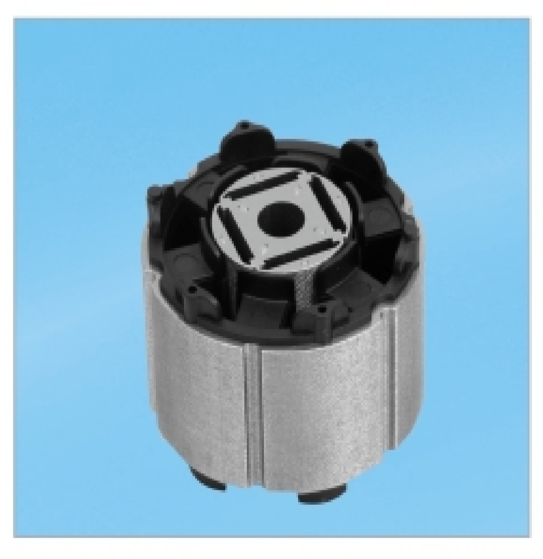
Below is a high-level technical overview of the key steps involved:
1. Design & Simulation
-
Electromagnetic Design:
Use software (e.g., ANSYS Maxwell, Motor-CAD, JMAG) to optimize:-
Stator segment shape (U/T/I-core)
-
Rotor magnet arrangement (surface-mounted/interior)
-
Windings (concentrated vs. distributed)
-
-
Thermal Analysis:
Model heat dissipation paths between segments. -
Structural Analysis:
Ensure mechanical integrity under high torque/vibration.
2. Stator Manufacturing
a) Segment Fabrication
-
Lamination Stamping:
-
Laser-cut or stamp thin silicon steel sheets into U/T/I-core laminations.
-
Coat laminations with insulation (e.g., C5 coating).
-
-
Stacking & Bonding:
-
Stack laminations into individual tooth segments.
-
Bond using epoxy, welding, or interlocking features.
-
b) Coil Winding
-
Pre-winding:
Wind copper wire (round or rectangular) around each segment using automated needle winders.
Key advantage: Achieves >70% slot fill (vs. ~45% in traditional stators). -
Insulation:
Add slot liners and impregnate with resin (varnish) for thermal/electrical protection.
c) Stator Assembly
-
Segments Alignment:
Arrange pre-wound segments into a ring using precision jigs. -
Structural Support:
-
Encase segments in a thermoplastic composite ring (injection-molded).
-
Or use a metal housing with adhesive/epoxy.
-
-
Termination:
Connect segment coils into phases (star/delta configuration).
3. Rotor Manufacturing
-
Core Assembly:
Stack steel laminations onto a shaft. -
Magnet Mounting:
-
Glue or sleeve neodymium (NdFeB) magnets onto the rotor surface.
-
Use Halbach array for higher flux density.
-
-
Balancing:
Dynamically balance rotor to minimize vibration.
4. Motor Integration
-
Assembly:
Insert rotor into stator with precise airgap (0.3–0.8 mm typical). -
Bearings & Housing:
Install bearings (ball or sleeve) and enclose in aluminum/steel housing. -
Sensors:
Mount Hall sensors/encoders for commutation feedback.
5. Controller & Testing
-
Custom BLDC Driver:
Design an ESC (Electronic Speed Controller) with:-
FOC (Field-Oriented Control) for smooth torque.
-
Thermal protection for high-current operation.
-
-
Validation Tests:
-
Performance: Torque-speed curves, efficiency maps.
-
Durability: Vibration, thermal cycling, overload tests.
-
Key Challenges & Solutions
| Challenge | Solution |
|---|---|
| Segment Alignment | Precision fixtures + laser alignment systems |
| Inter-Segment Flux Leakage | Optimized lamination shapes + FEM simulation |
| Mechanical Stability | Composite encapsulation + structural rings |
| High-Frequency Losses | Thin laminations (0.2–0.35 mm) |
Tools & Materials Needed
-
Software: ANSYS, SolidWorks, Altium Designer (for controller).
-
Equipment: Laser cutter, winding machines, impregnation oven, dynamometer.
-
Materials: Silicon steel laminations, NdFeB magnets, enameled copper wire, high-temp epoxy.
Why This Isn’t DIY-Friendly
-
Requires $100k+ in specialized equipment.
-
Tolerance demands: ±0.05 mm for segments.
-
Safety risks: High-voltage winding/controller testing.
Learning Alternatives
-
Study Open-Source Projects:
-
MotorDesignLib (Matlab-based motor sim).
-
-
Build a Traditional BLDC Motor:
-
Start with kits (e.g., from PCBWay or T-Motor).
-
-
Experiment with Segmented Kits:
-
Companies like Infinitum offer demo units.
-
For commercial production, partner with motor factories (e.g., in Shenzhen, China) specializing in segmented stators. This technology is reshaping EVs and drones—mastering it demands deep electromechanical engineering knowledge! ?⚡
What is vehicle door lock BLDC Motor?
Why BLDC Motor is important for wall breaker?
Related Article


