
What is two phases BLDC Motor?
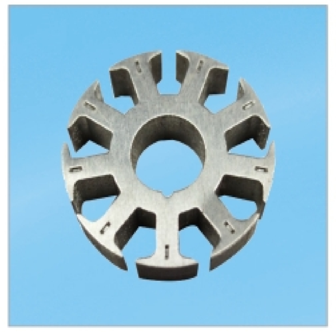
Here's a breakdown of its key aspects:
-
Basic Structure:
-
Stator: Has two sets of windings (Phase A and Phase B), physically arranged at 90° to each other around the stator core.
-
Rotor: Typically uses permanent magnets (e.g., Neodymium), with alternating North and South poles. Common configurations are 2-pole or 4-pole.
-
-
How it Works (Principle of Operation):
-
Commutation: The motor controller sequentially energizes the two phases in a specific pattern (e.g., A+, B+, A-, B-) to create a rotating magnetic field.
-
Torque Production: The rotor's permanent magnets align with and try to follow this rotating stator field, generating torque.
-
Position Sensing: Hall effect sensors (usually two, placed 90 electrical degrees apart) detect the rotor's position and provide feedback to the controller to time the commutation correctly. Sensorless control is also possible but often trickier than with three-phase motors.
-
-
Driving Methods:
-
Unipolar Driving (Common): Often uses windings with a center tap. Each phase is driven by connecting one end to power/ground while the center tap is connected to the opposite (power/ground). This requires only two low-side switches per phase (total 4 switches).
-
Bipolar Driving: Requires a full H-bridge driver for each phase (total 4 switches per phase = 8 switches). This allows more flexible current control but is more complex and expensive. Less common for basic two-phase motors.
-
-
Key Characteristics & Differences vs. Three-Phase BLDC:
-
Simpler Drive Electronics: Requires fewer power switches (typically 4 for unipolar drive vs. 6 for a standard three-phase inverter).
-
Potentially Lower Cost: Fewer switches and simpler control logic can lead to lower system cost for very low-power applications.
-
Higher Torque Ripple: This is the most significant drawback. Torque is produced most strongly when the stator field is directly aligned with a rotor pole (at 0°, 90°, 180°, 270°). Torque dips significantly between these points (at 45°, 135°, 225°, 315°) because only one phase is actively pulling the rotor at those instants. This results in four torque dips per electrical cycle.
-
Vibration & Noise: The inherent torque ripple causes more vibration and audible noise compared to three-phase motors.
-
Lower Efficiency & Power Density: Generally less efficient and produces less torque for the same size/weight compared to a well-designed three-phase motor due to the torque ripple and potentially less optimal use of copper.
-
Commutation Points: Commutation occurs every 90 electrical degrees (vs. every 60 degrees in three-phase).
-
-
Typical Applications:
-
Where very low cost and extreme simplicity are paramount, and torque ripple/noise are acceptable.
-
Very low-power devices: Small cooling fans (e.g., computer case fans), tiny pumps, simple toys, low-cost appliances (e.g., small blenders, basic power tools), some positioning actuators.
-
Applications where space for electronics is extremely constrained (due to fewer switches).
-
In Summary:
A two-phase BLDC motor is a simpler, potentially lower-cost alternative to the ubiquitous three-phase BLDC motor, using only two stator windings driven 90 degrees apart. Its main advantages are simpler/cost-effective drive electronics. However, its significant disadvantages are higher torque ripple, increased vibration/noise, and lower efficiency/power density. Because of these drawbacks, three-phase BLDC motors dominate most applications where performance, smoothness, and efficiency are important. Two-phase motors are primarily found in very low-cost, low-power applications where their limitations are tolerable.
Why two phases BLDC Motor is important?
How to make Blower motor in BLDC Motor classification?
Related Article


