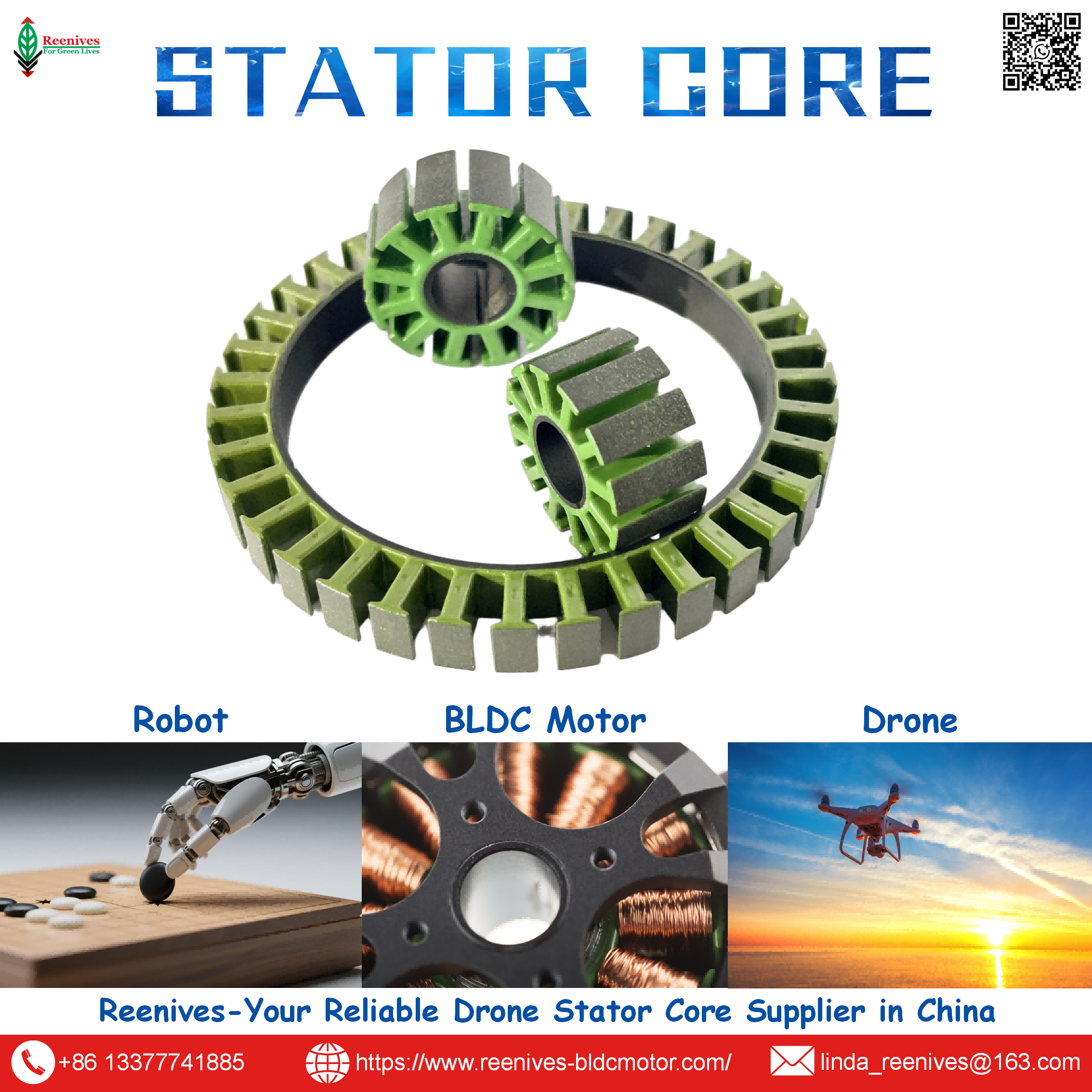
Reenives: Global Leading Drone Stator Motor Electric Core Supplier

Stator Motor Electric: What Separates a Rated Drone Stator from a Reliable One — and Why the Difference Is in the Data
Most drone motor failures that get blamed on the ESC or the battery started in the stator — specifically in the stator’s electric performance. The propeller is optimized, the controller is rated correctly, the cells are fresh, and the motor still loses thrust after ten minutes or trips on overcurrent at peak torque. Engineers often treat the stator core as a commodity: a stack of steel with some copper in it. That assumption is the root cause. The stator is where electrical input becomes mechanical output, and its electric performance — iron loss, insulation integrity, dimensional control, and phase balance — determines whether the motor meets its thrust curve in the field or only on the datasheet.
This guide is written for the procurement engineer who has to audit a stator supplier and the R&D engineer who has to defend a selection decision. It defines what “Stator Motor Electric” performance means in measurable terms, separates the stator architectures and their electrical trade-offs, presents published core-loss and coating data with verification standards, and closes with the specification fields that turn a supplier claim into a testable requirement. Every figure below is tied to a named test method or a published source, so it can be written into an RFQ rather than debated.

In this guide — jump to the section your project needs:
- What Does “Stator Motor Electric” Mean? The Four Electrical Metrics That Define the Stator
- Stator Architectures and Their Electrical Trade-Offs: Segmented, Integrated Circular, Split-Tooth
- Parameters and Verification: Iron Loss, Coating Dielectric, Stacking Factor, Concentricity
- Application Profiles: Which Electric Parameter Binds Which UAV Mission
- A 5-Step Stator Motor Electric Verification Workflow
- FAQ: Core Loss, Coating, Stacking Factor, and Supplier Data Credibility
- Summary: The Electric Data Is the Product
What Does “Stator Motor Electric” Mean? The Four Electrical Metrics That Define the Stator
“Stator Motor Electric” is not a product category; it is the set of electrical properties through which the stator contributes to motor performance. Four metrics capture that contribution, and each one can be specified, measured, and audited.
| Electrical Metric | What It Governs in the Motor | How It Is Measured | Why It Matters for a Drone |
|---|---|---|---|
| Iron loss (core loss) | Heat generated in the steel as the magnetic field cycles | Epstein frame per IEC 60404-2; reported in W/kg at a defined flux density and frequency | At high electrical frequency, core loss is a direct tax on flight time and thermal margin |
| Insulation dielectric strength | Ability of the interlamination and winding coating to block short circuits | ASTM D149; reported in volts, with temperature class per IEC 60085 | Coating failure produces local hot spots and interlamination short circuits that no winding redesign can fix |
| Stacking factor | Effective magnetic density of the finished stack versus solid steel | Weight/dimension method on the finished stack | A loose stack wastes the flux density the lamination grade was selected to provide |
| Concentricity / air-gap uniformity | Uniformity of the magnetic pull around the rotor | Metrology on stator bore and rotor OD; reported as TIR or tolerance | Eccentricity produces vibration and bearing load, which feeds back into further eccentricity |
The reason these four belong together is that they interact. A 0.20 mm low-loss lamination delivers its published iron loss only if the stack holds its stacking factor; a high stacking factor is wasted if burrs pierce the interlamination coating and create short circuits; and a coating that survives dielectric testing in a lab can still fail in a vibrating, thermally cycling airframe if concentricity is poor and the air gap loads the bearing unevenly. Stator Motor Electric performance is a system property, not a single number on a certificate.
Procurement translation: a stator datasheet that lists “low core loss” without naming the test standard, the flux density, and the frequency is not a specification. The same applies to “high dielectric strength” without the test method and the temperature class. The four metrics above become auditable only when each is paired with a standard: IEC 60404-2 for core loss, ASTM D149 for dielectric strength, weight/dimension method for stacking factor, and a stated metrology method for concentricity.
Stator Architectures and Their Electrical Trade-Offs: Segmented, Integrated Circular, Split-Tooth
Stator architectures are not cosmetic variations. Each one changes the electrical loss profile, the winding resistance, and the manufacturability of the electric performance.
| Architecture | Construction | Electrical Advantage | Electrical Trade-Off | Typical Drone Fit |
|---|---|---|---|---|
| Segmented stator core | Modular segments wound separately before assembly | Simplified winding, good slot fill, suitable for thin laminations | Segment-to-segment concentricity and phase balance must be controlled at assembly | 5–7 inch FPV racing drones |
| Integrated circular laminated stack | One-piece stamped ring, interlocked or welded | Dimensional rigidity and thermal mass; predictable magnetic circuit | Less flexibility for custom slot geometry without a dedicated die | Heavy-lift agricultural and logistics UAVs |
| Split-tooth design | Separate teeth for maximum copper fill before insertion | Copper fill factor above 50%, lower resistance for a given slot area | More assembly steps; tooth-to-yoke interface must maintain magnetic continuity | High-power logistics drones (15–20 kW peak) |
The electrical trade-offs are specific. Segmented cores simplify winding and suit the thin laminations needed for high-RPM FPV motors, but the assembly step introduces a phase-balance risk: if segment resistances are not matched, the motor draws uneven current across phases, which in a closed-loop controller appears as torque ripple and in a delta termination appears as circulating current. Integrated circular stacks avoid that interface but commit the design to a single die geometry, which raises tooling cost for custom slot profiles. Split-tooth designs push copper fill above 50% and lower resistance, but the tooth-to-yoke joint is a magnetic discontinuity that must be controlled or the flux-density benefit is lost.
Reenives supplies all three architectures and matches the recommendation to the power class and operating frequency rather than to a catalog preference. For FPV and racing platforms, the 0.20 mm lamination in a segmented core reduces eddy-current loss at the high electrical frequencies those motors run. For agricultural spraying drones, the integrated circular stack provides the thermal mass and wide slots needed for thicker copper windings at low RPM. For logistics and eVTOL platforms, the split-tooth design targets the copper fill and efficiency required at cruise power.

Parameters and Verification: Iron Loss, Coating Dielectric, Stacking Factor, Concentricity
Iron loss: the frequency-dependent tax
Iron loss has two components. Hysteresis loss is proportional to frequency and the grade’s coercivity; eddy-current loss is proportional to the square of both lamination thickness and frequency. In a 50 Hz industrial motor, a 0.50 mm lamination is tolerable. In a drone motor running at 15,000 RPM with multiple pole pairs, the electrical frequency is far higher and the eddy-current penalty for thick laminations becomes severe. Published small-motor data puts the mechanism in numbers: switching from 0.35 mm to 0.20 mm laminations reduces eddy-current loss by approximately 67% at the same flux density.
| Lamination Thickness | Typical Grade | Iron Loss @ 1.0 T / 400 Hz | Best Fit | Relative Cost |
|---|---|---|---|---|
| 0.35 mm | 35W300 / 35W270 | ~28–35 W/kg (published range) | Industrial servo ≤ 3,000 RPM, cost-sensitive designs | Low |
| 0.20 mm | 20W1200H / 20W1500H; Reenives 20WTG1300 | ~10–14 W/kg (published range); Reenives ≤ 8.9 W/kg | High-speed motors ≥ 8,000 RPM, UAV, FPV | High |
Published range: HIMAGNET small-motor lamination guide, 2026. Reenives specification: ≤ 8.9 W/kg at 1.0 T / 400 Hz for 20WTG1300, measured by Epstein frame per IEC 60404-2.
The motor-level consequence is not abstract. In a 60 W servo motor core with 0.35 mm laminations generating 8 W of iron loss at operating speed, switching to 0.20 mm reduces that loss to approximately 2.5 W — a 5.5 W saving that translates to an estimated 15–25°C reduction in steady-state winding temperature and permits roughly 8–12% higher continuous torque before the thermal limit. In a drone, that same mechanism is the difference between a hover that holds its thrust curve and one that sags as the winding heats and resistance rises.
Coating dielectric strength and temperature class
The interlamination coating is the stator’s electrical insulation barrier. Reenives specifies C5 epoxy powder coating with a nano-ceramic thermal barrier, rated for >180°C continuous operation and >2000 V dielectric strength, tested per ASTM D149 / IEC 60085. C6 grade is available where superior thermal conductivity and corrosion resistance are required, with salt-spray resistance beyond 96 hours. These figures matter because coating failure is not gradual: a burr that pierces the coating during stacking creates a local short circuit that generates eddy currents and a hot spot, and that hot spot degrades the surrounding insulation, propagating the fault.
Stacking factor and concentricity: the manufacturing control of electrical performance
Reenives publishes interlocked stacks at ≥ 98.2% stacking factor and bonded cores at 98.6%, with a stack height tolerance of ± 0.015 mm for precision-matched sets. For drone BLDC motors, concentricity below 0.03 mm keeps the air gap uniform; Reenives specifies ≤ 0.02 mm on drone-grade cores. The electrical consequence of stacking factor is direct: moving from a 96% to a 98% stacking factor increases effective magnetic flux density by roughly 6% without changing the steel grade. The electrical consequence of concentricity is indirect but equally real: a non-uniform air gap produces uneven magnetic pull, which loads the bearing, and bearing wear increases eccentricity — a feedback loop that ends in vibration, noise, and premature failure.
Verification discipline: ask three questions for every electrical parameter. What is the test standard? (IEC 60404-2 for core loss, ASTM D149 for dielectric, weight/dimension for stacking factor.) Was the measurement made on raw material or finished stack? (The finished stack is the auditable product.) What production control maintains the value? (Stacking method, burr height limit, phase-resistance matching.) A supplier who can answer all three is describing a process; one who can answer only the first is describing a brochure.
Application Profiles: Which Electric Parameter Binds Which UAV Mission
| UAV Mission Class | Binding Electric Parameter | Why | Specification to Write |
|---|---|---|---|
| FPV racing / high-RPM | Iron loss at high electrical frequency | Electrical frequency scales with RPM; eddy-current loss dominates and becomes heat at the winding | 0.15–0.20 mm low-loss grade; core loss ≤ 8.9 W/kg @ 1.0 T / 400 Hz; finished-stack report |
| Agricultural spraying UAV | Coating dielectric and thermal class | Continuous duty near thermal limit; chemical exposure and high ambient temperature accelerate insulation aging | C5 epoxy with nano-ceramic barrier, >180°C, >2000 V; salt-spray resistance where relevant |
| Inspection / survey drone | Concentricity and stacking factor | Precision hover requires smooth torque; vibration and cogging degrade sensor payload stability | Concentricity ≤ 0.02 mm; stacking factor ≥ 98.2% interlocked |
| Heavy-lift / logistics UAV | Stacking factor and phase balance | High continuous torque at large propeller diameter; a loose stack or unbalanced phase wastes the flux density the design paid for | Stacking factor ≥ 98.2%; phase-resistance matching; matched stator-rotor pair |
The pattern is that the binding electric parameter tracks the mission’s dominant loss or reliability mechanism. For FPV, it is iron loss at frequency. For agricultural platforms, it is insulation survival under thermal and chemical stress. For inspection, it is dimensional control that suppresses vibration. For heavy-lift, it is the manufacturing control that preserves flux density and phase balance. A stator specified against the wrong parameter can pass inspection and still underperform in the field, because the mechanism that limits the mission was never the one being measured.

A 5-Step Stator Motor Electric Verification Workflow
- Start from the electrical frequency at the operating point, not from the motor nameplate. Calculate electrical frequency as RPM × pole pairs ÷ 60. A 12N14P motor at 15,000 RPM runs at 1,750 Hz electrical. That number determines whether 0.35 mm or 0.20 mm is the appropriate lamination grade, because eddy-current loss scales with the square of both thickness and frequency.
- Specify iron loss with the test standard, the flux density, and the frequency. A requirement of “core loss ≤ 8.9 W/kg at 1.0 T / 400 Hz, measured by Epstein frame per IEC 60404-2 on the finished stack” is auditable. “Low core loss” is not. Reenives publishes this value for its 20WTG1300 0.20 mm grade; the finished-stack condition is what separates a material property from a product specification.
- Specify the coating class with dielectric strength and temperature class. Name the coating (C5 epoxy with nano-ceramic barrier or C6), the dielectric requirement (>2000 V per ASTM D149), the temperature class (>180°C continuous per IEC 60085), and the environmental exposure where relevant (salt-spray resistance beyond 96 hours for C6). Coating integrity is the electrical barrier that prevents interlamination short circuits and winding-to-core faults.
- Specify stacking factor and concentricity on the finished part. Require stacking factor ≥ 98.2% for interlocked stacks (or 98.6% for bonded), stack height tolerance ± 0.015 mm for matched sets, and concentricity ≤ 0.02 mm for drone-grade cores. These are the manufacturing controls that determine whether the lamination grade’s electrical performance reaches the installed motor.
- Audit the production control that maintains the values, not just the values themselves. Ask for burr height limits, interlamination resistance results, phase-resistance matching data, and the sampling plan used for core-loss verification. A supplier who tests finished stacks and controls burr height is managing the electrical performance; a supplier who ships mill certificates is transferring the risk to you.
FAQ: Core Loss, Coating, Stacking Factor, and Supplier Data Credibility
What does “Stator Motor Electric” performance actually mean for a drone motor?
It means the stator’s contribution to the motor’s electrical-to-mechanical conversion: how much input power becomes torque rather than heat. The measurable quantities are iron loss at the operating electrical frequency, winding resistance and phase balance, insulation dielectric strength, and the dimensional control that keeps the air gap uniform. A stator can pass a visual inspection and still fail these electrical criteria — which is why the specification must name them.
Source: BLDC stator core electrical performance framework, combining core loss, insulation, stacking, and dimensional metrics.
How much iron loss does a 0.20 mm lamination save compared with 0.35 mm in a drone stator?
Published small-motor data places 0.20 mm high-grade silicon steel at roughly 10–14 W/kg at 1.0 T / 400 Hz, while 0.35 mm material runs roughly 28–35 W/kg at the same test point — a difference driven by eddy-current loss scaling with the square of lamination thickness. Reenives publishes ≤ 8.9 W/kg for its 20WTG1300 0.20 mm grade at 1.0 T / 400 Hz, measured by Epstein frame per IEC 60404-2. In a controlled swap on a standard drone BLDC motor, moving from 0.35 mm to 0.20 mm improved efficiency by 1–2% and reduced core and winding temperature by more than 10°C.
Source: HIMAGNET small-motor lamination guide, 2026; Reenives 20WTG1300 specification; Reenives controlled motor test data.
What dielectric strength and temperature rating should a drone stator coating provide?
For UAV and high-load brushless motors, Reenives specifies C5 epoxy powder coating with a nano-ceramic thermal barrier, rated for >180°C continuous operation and >2000 V dielectric strength, tested per ASTM D149 / IEC 60085. C6 grade is available where superior thermal conductivity and corrosion resistance are required, with salt-spray resistance beyond 96 hours. These are not cosmetic choices: coating integrity is what prevents interlamination short circuits and winding-to-core faults under thermal cycling.
Source: Reenives C5/C6 epoxy coating specification data; ASTM D149 and IEC 60085 test standards.
What stacking factor and concentricity should a drone stator core hold?
Reenives publishes interlocked stacks at ≥ 98.2% stacking factor and bonded cores at 98.6%, with a stack height tolerance of ± 0.015 mm for precision-matched sets. For drone BLDC motors, concentricity below 0.03 mm keeps the air gap uniform; Reenives specifies ≤ 0.02 mm on drone-grade laminated stator cores. A loose stack wastes the flux density the steel grade was selected for, and an eccentric bore produces uneven magnetic pull that manifests as vibration and accelerated bearing wear.
Source: Reenives stator lamination specification table; drone concentricity requirement from Reenives UAV stator core engineering data.
Is core loss measured on the raw steel or on the finished stator stack?
The auditable measurement is on the finished stack. IEC 60404-2 defines the Epstein-frame method for specific total loss of electrical steel at 50 Hz / 1.5 T, with the stipulation that no external stress be exerted on the specimen. Stamping and stacking introduce stress and burrs that the Epstein specimen does not experience. A supplier who reports only a mill certificate is reporting a material property; a supplier who reports finished-stack core loss is reporting the product you will install.
Source: IEC 60404-2 Epstein frame measurement conditions; Reenives finished-stack verification practice.
How can I verify that a stator supplier’s electrical data is credible before ordering?
Three verification layers turn a claim into evidence. First, ask for the test method and standard: Epstein frame per IEC 60404-2 for core loss; ASTM D149 for dielectric strength; micrometer/SPC control for lamination thickness. Second, ask whether the reported value is on raw material or finished stack. Third, ask for the production control that maintains the value — stacking method, burr height limit, phase-resistance matching, and interlamination resistance. A supplier who can answer all three is describing a process; one who can answer only the first is describing a brochure.
Source: Stator supplier qualification framework combining test standards, measurement location, and production control evidence.
Summary: The Electric Data Is the Product
“Stator Motor Electric” is not a marketing phrase. It is the set of four measurable properties — iron loss at the operating frequency, insulation dielectric strength, stacking factor, and air-gap concentricity — through which the stator determines whether a drone motor converts electrical input into thrust or into heat. The published data is specific: 0.20 mm low-loss silicon steel at roughly 10–14 W/kg (Reenives ≤ 8.9 W/kg) versus 0.35 mm at roughly 28–35 W/kg at 1.0 T / 400 Hz; a 1–2% efficiency gain and >10°C temperature reduction from a 0.35 mm to 0.20 mm swap; C5 coating rated >2000 V and >180°C; interlocked stacking factor ≥ 98.2%; concentricity ≤ 0.02 mm.
The procurement lesson is that these numbers are only meaningful when paired with their test standards and their measurement location. A core-loss figure without IEC 60404-2 is a claim; a figure measured on raw steel rather than the finished stack is a material property, not a product specification. The supplier worth qualifying is the one who can name the standard, state whether the value is on the finished stack, and describe the production control — burr height, phase balance, interlamination resistance — that keeps the value in every shipment.
Need a Stator Motor Electric specification you can audit?
Reenives supplies drone and brushless motor stator cores with published electrical data: 0.20 mm 20WTG1300 at ≤ 8.9 W/kg @ 1.0 T / 400 Hz (IEC 60404-2), C5 epoxy coating at >2000 V and >180°C (ASTM D149 / IEC 60085), interlocked stacking factor ≥ 98.2%, and concentricity ≤ 0.02 mm. Finished-stack verification data, matched stator-rotor pairs, and free samples are available for qualified engineering evaluations.
WhatsApp: +86-13377741885
Email: linda_reenives@163.com
Official website: www.reenives-bldcmotor.com
Dongguan Runlu Motor Technology Co., Ltd.
Reenives — Drone Motor One-Stop Solution Supplier
Reenives is a professional drone stator core manufacturer, founded in 2022. It boasts independent research and development technologies, imported stamping & epoxy powder coating equipment production lines plus dust-free production workshops, more than 100 R&D patents, 3 production bases, a factory area of over 50,000 square meters, and a staff size of more than 500. From production to sales, we support bulk purchasing, private mould development, and sample making, and can provide tailor-made perfect solutions for your production and usage scenarios. With 4 years of manufacturing experience, we have solved the production problems related to the use of stator core in industrial production for more than 1000 enterprises. We can ship globally (with complete export qualifications). Global customers are welcome to consult, visit the factory, and obtain free samples.
Core loss ≤ 8.9 W/kg @ 1.0 T / 400 HzC5 / C6 epoxy coating>2000 V dielectric strengthStacking factor ≥ 98.2%Concentricity ≤ 0.02 mmGlobal export qualifications
Reenives: Drone Motor Stator and Rotor Supplier in China
How Much Drone Motor Stator Price?
Related Article