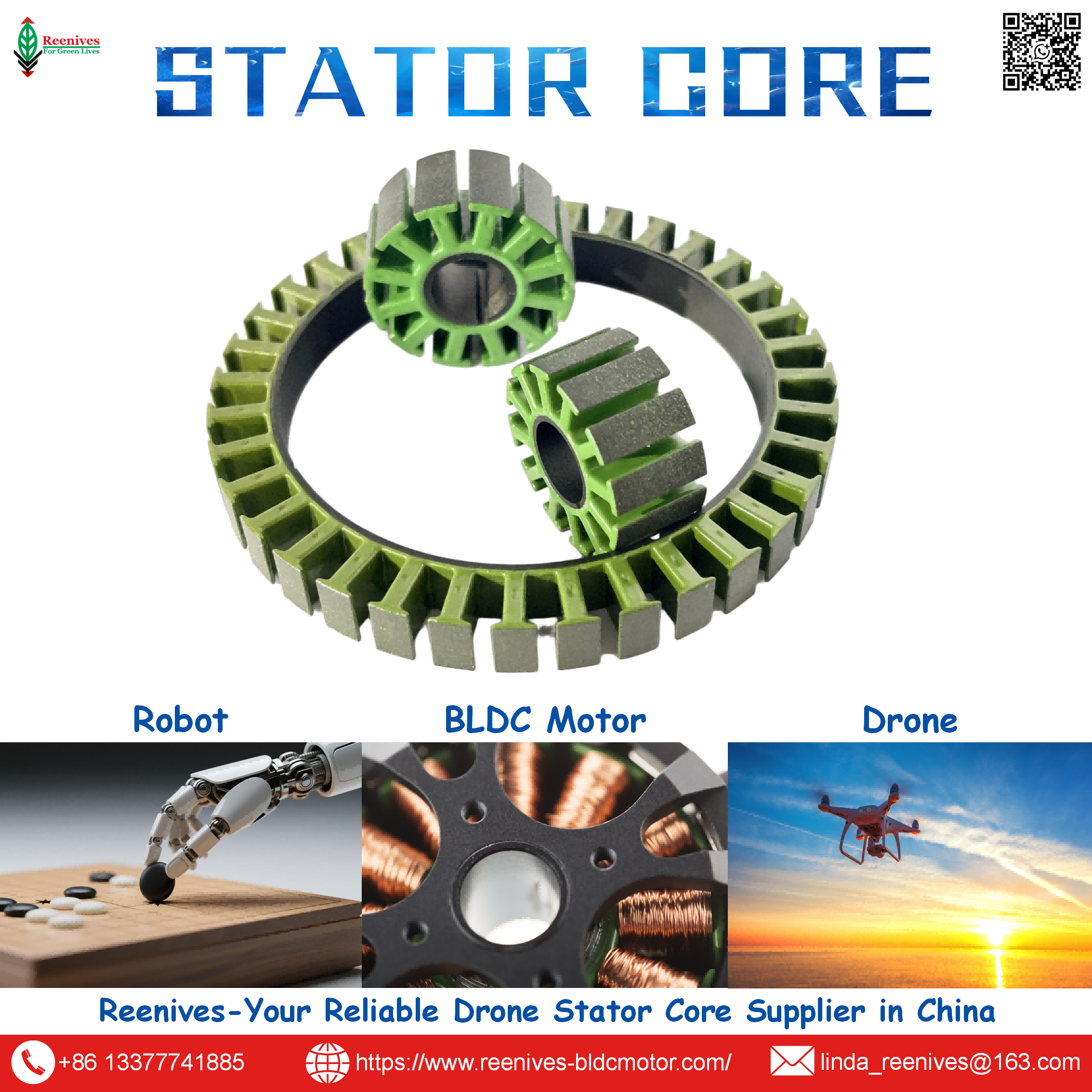
How Many Different Types of Stator in Drone Motor?

How Many Different Types of Stator in Drone Motor? The Answer Is Four Axes — Not One Number
Ask five suppliers “how many different types of stator are there for drone motors” and you will get five answers, all of them incomplete. One will list slotted and slotless. Another will say radial-flux and axial-flux. A third will insist the real distinction is 12N14P versus 24N22P. They are not wrong — they are each describing one axis of a four-axis classification space, and the confusion costs procurement teams real money when they compare quotes that sound identical but describe different machines.
The practical consequence is straightforward: a stator specification that names only “12N14P” or only “0.20 mm lamination” is not a specification — it is one coordinate in a four-dimensional space. The same 12N14P slot-pole combination can be built as a radial-flux slotted laminated core or as an axial-flux PCB stator, and those two products will differ in torque density, iron loss, thermal path, and unit cost. This guide separates the axes, gives the published data for each, and closes with a five-step workflow that turns the taxonomy into a purchase order.

In this guide — jump to the section your project needs:
- What Is a Stator Type? The Four Axes That Define Every Drone Stator
- The Four Classification Axes in Detail: Flux Direction, Core Construction, Slot-Pole, Winding Topology
- Parameters That Separate the Types: Core Loss, Stacking Factor, Concentricity, and Slot-Pole Data
- Application Profiles: Which Stator Type Binds Which UAV Mission
- A 5-Step Workflow: From Mission Requirement to Stator Type Specification
- FAQ: Slot-Pole Choice, Lamination Thickness, Stacking Factor, and Winding Topology
- Summary: Name the Axis Before You Compare the Quote
What Is a Stator Type? The Four Axes That Define Every Drone Stator
“Stator type” is not a single categorical variable. A drone stator is fully described by its position on four independent axes, and changing any one of them changes the motor’s performance envelope.
| Axis | Options | What It Changes |
|---|---|---|
| 1. Flux direction | Radial-flux / Axial-flux | Flux path length, axial length vs diameter, end-winding volume |
| 2. Core construction | Slotted laminated / Slotless / Coreless / SMC / PCB | Cogging torque, iron loss, torque density, thermal path, unit cost |
| 3. Slot-pole combination | 9N12P / 12N14P / 18N24P / 24N22P / 24N28P / custom | Winding factor, cogging profile, torque density, suitable RPM range |
| 4. Winding topology | Concentrated / Distributed | Back-EMF waveform, end-winding weight, copper resistance, MMF smoothness |
The reason this matters commercially is that two motors can match on three axes and differ on the fourth, and the quote will not tell you. A radial-flux, slotted laminated, 12N14P stator with concentrated winding is the classic drone outrunner configuration. But the same slot-pole and winding choice can be built as an axial-flux machine, where the flux crosses the air gap parallel to the shaft rather than perpendicular to it, and the stator becomes a flat disc rather than a cylindrical stack. The axial-flux variant can offer shorter axial length and higher power density because it eliminates the yoke and the end-winding overhang — but it requires precise rotor construction and changes the manufacturing route entirely.
The classification is not academic. When a procurement engineer asks “how many types,” the useful response is not a count — it is a request to name the four axes and specify the option on each. That single discipline eliminates most quote-comparison errors before the samples are even ordered.
The Four Classification Axes in Detail: Flux Direction, Core Construction, Slot-Pole, Winding Topology
Axis 1 — Flux direction: radial versus axial
In a radial-flux machine, the flux from the rotor magnets crosses the air gap in a radial direction, perpendicular to the shaft. This is the dominant construction in drone outrunners: a cylindrical stator inside a rotor bell, with the magnetic circuit symmetrical about the shaft axis. Radial-flux machines are the default for UAV propulsion because of design maturity, manufacturability, and the fact that the radial magnetic circuit produces low axial vibration and suits low-to-moderate speed operation with high torque.
In an axial-flux machine, the flux crosses the air gap parallel to the shaft. The stator is typically a flat disc, and the rotor carries magnets on one or both flat faces. Published comparison for UAV propulsion notes that the radial-flux permanent magnet motor has received more priority due to design and construction sustainability, while the axial-flux variant offers higher speed, power density, lower weight, and greater efficiency because of its shorter flux path and the absence of end-turn winding. The trade is manufacturing complexity: axial-flux rotors require precise construction and the stator often uses SMC, PCB, or tape-wound cores rather than conventional stamped laminations.
Axis 2 — Core construction: the five families
| Core Construction | How It Is Built | Cogging | Iron Loss | Torque Density | Typical Drone Role |
|---|---|---|---|---|---|
| Slotted laminated | Stacked electrical steel sheets with cut slots; copper inserted into slots | Present, can be reduced by skew or slot design | Dependent on grade and thickness | Highest | Mainstream UAV outrunners |
| Slotless | No teeth; windings placed in the air gap without slot openings | Essentially eliminated | Lower than slotted at high frequency | Lower — larger effective air gap | High-speed, low-cogging precision drives |
| Coreless | No steel core; windings on a non-magnetic support | Zero | Zero iron loss | Lowest continuous | Micro drones, high-speed low-power propulsion |
| SMC (soft magnetic composite) | Iron powder particles with surface insulation, molded into 3D shapes | Design-dependent | Comparable to laminated at high frequency; higher hysteresis | Moderate — limited by lower saturation flux density | Axial-flux AFPM cores, 3D flux paths |
| PCB stator | Copper traces etched onto multilayer PCB; no laminated core | Reduced / near zero | Core-loss-free, but copper-loss-limited | Low-to-moderate, thermally limited | Low-voltage, compact axial-flux designs |
The published comparison data is specific. For a 14-pole, 12-slot axial-flux machine, the laminated core was more efficient at low operating speeds, while at higher operating frequencies the SMC and laminated cores had comparable efficiencies — attributed to increased eddy-current losses in the laminated steel as frequency rose. A PCB stator compared with a laminated stator at the same output power was more efficient and compact, but had significant thermal limitations on achieving higher current densities, making it promising for low voltage and current ratings but challenging at elevated voltages and current densities.
SMC has its own trade-off profile: it offers high magnetic flux densities, ease of manufacturing for AFPM cores, and reduced eddy-current losses due to high electrical resistivity, but it is more expensive than steel sheets and is most beneficial when strong magnets produce high flux density in the air gap. Its drawbacks include lower saturation flux density requiring a thicker stator, and higher hysteresis loss due to higher magnetic coercive force than electrical laminations.
Axis 3 — Slot-pole combination: the drone-specific decision
The slot-pole combination is the most drone-specific choice on the four axes, because it directly sets the winding factor, the cogging torque profile, and the mechanical symmetry of the machine.
| Configuration | Slots | Poles | Winding Factor | Cogging | Drone Application |
|---|---|---|---|---|---|
| 12N14P | 12 | 14 | 0.933 | Very low | Drones, multirotors — the default |
| 9N12P | 9 | 12 | — | Low | High-RPM racing, lightweight builds |
| 18N24P | 18 | 24 | — | Low | High torque density, heavy-lift |
| 24N22P | 24 | 22 | 0.949 | Extremely low | Gimbal motors, smooth-priority platforms |
| 24N28P | 24 | 28 | — | Low | Heavy-lift / eVTOL |
Source: BLDC slot/pole combination reference table; Reenives stator slot/pole configuration data for 9N12P, 12N14P, 18N24P, and 24N28P topologies.
Why 12N14P dominates is structural. The near-perfect winding factor of 0.933 means the winding produces the useful fundamental magnetic field efficiently. The concentrated winding pattern wraps each coil around a single tooth, shortening the end turns. And the slight slot-pole asymmetry means the magnets never align with all teeth simultaneously, dramatically reducing cogging — critical for smooth gimbal operation and responsive flight control. The valid-combination rules are equally important: slot count must be divisible by three, slot count must not equal pole count, and a low greatest common divisor relative to the slot count reduces cogging amplitude.
Axis 4 — Winding topology: concentrated versus distributed
The fourth axis is often invisible in a stator datasheet, yet it determines the back-EMF waveform and the copper mass. Concentrated winding wraps each phase coil around a single stator arm, producing a trapezoidal back-EMF characteristic of BLDC motors, with short end windings and low copper weight. It is the standard choice for fractional-slot concentrated winding (FSCW) machines, and published examples explicitly include drone propulsion motors and robotic joint motors. Distributed winding spreads phase coils along multiple arms, producing a more sinusoidal MMF and back-EMF characteristic of brushless AC (BLAC) motors; it is used where smooth MMF distribution matters more than end-winding compactness.
The distinction is not a quality ranking. A concentrated winding drone motor with a trapezoidal back-EMF is designed for the commutation strategy of a BLDC controller. A distributed winding with sinusoidal back-EMF pairs with field-oriented control. Specifying “concentrated” when the ESC expects sinusoidal drive, or the reverse, produces a motor that runs but does not run at its design efficiency.

Parameters That Separate the Types: Core Loss, Stacking Factor, Concentricity, and Slot-Pole Data
The classification axes are qualitative until they are tied to measurable parameters. The four below are the ones that appear in supplier qualification reports and bench comparisons, and each maps back to a specific axis.
Core loss by lamination thickness: the Axis 2 parameter
For slotted laminated cores, the steel grade and thickness set the iron loss that becomes motor heat at the operating electrical frequency. Reenives publishes typical core loss at 1.0 T / 400 Hz of ≤ 8.2 W/kg for 0.20 mm grade and ≤ 12 W/kg for 0.35 mm grade, measured per IEC 60404-2 with third-party SGS report 2024-3789. Independent grade data places 0.20 mm high-silicon material at roughly 10–14 W/kg at the same test point, and 0.35 mm material at roughly 28–35 W/kg, with the thinner grade recommended for high-speed motors above 8,000 RPM and UAV applications. The motor-level consequence: at high electrical frequency, the 0.20 mm grade is not an upgrade, it is the baseline for drone-class performance.
Stacking factor and stack tolerance: the manufacturing parameter that cuts across axes
A stator core stamped from the correct grade can still underperform if the stack is loose. Reenives publishes a typical stacking factor of ≥ 97.0% (target 97.5%) by the weight/dimension method, and a stack height tolerance of ± 0.015 mm for precision-matched sets. Industry benchmarks for eVTOL-class lamination stacking cite stacking factors above 96% and burr control below 10 μm as the threshold where electromagnetic performance stops being lost to manufacturing. Stacking factor is not an axis in the classification space — it is a quality dimension that applies to every slotted laminated stator regardless of which coordinate it occupies.
Concentricity: the parameter that connects stator type to vibration
Reenives specifies concentricity ≤ 0.02 mm for drone-grade laminated stator cores, with a custom outer diameter range of 18 mm to 210 mm for matched stator and rotor sets. A non-uniform air gap produces uneven magnetic pull, which manifests as vibration and bearing load. The eccentricity-to-bearing-failure chain is not type-specific — it applies equally to a 12N14P slotted core and a 24N28P heavy-lift core. What changes across stator types is how much the manufacturing route can hold: a stamped laminated stack can achieve tighter concentricity than a molded SMC core or a PCB stator, where board flatness and thickness variation become the tolerance drivers.
Slot-pole data: the Axis 3 parameter that determines cogging and winding factor
The winding factor and cogging profile are not opinions; they are computable from the slot and pole numbers. 12N14P delivers 0.933 winding factor with very low cogging; 24N22P delivers 0.949 with extremely low cogging and is used in gimbal motors. Published finite-element work on 14-pole/12-slot machines reports good output torque ripple and cogging torque performance, and stator design techniques — slot displacement, tooth notching, slot opening optimization, skewing — can reduce cogging by up to 60% when used in combination with rotor magnet skew. These are the levers available once the slot-pole coordinate is fixed.
Application Profiles: Which Stator Type Binds Which UAV Mission
The four-axis framework becomes useful when it is mapped to mission requirements. The table below translates each UAV class into the axis that is binding and the stator type that follows from it.
| UAV Mission Class | Binding Axis | Stator Type That Follows | Specification to Write |
|---|---|---|---|
| FPV racing / freestyle | Axis 3 (slot-pole) and Axis 2 (lamination) | Radial-flux, slotted laminated, 9N12P or 12N14P, 0.20 mm low-loss | 0.20 mm grade, core loss ≤ 8.2 W/kg @ 1.0 T / 400 Hz, low burr |
| Commercial survey / inspection UAV | Axis 1 (flux) and Axis 2 (core) | Radial-flux slotted laminated, 12N14P, 0.20 mm | Concentricity ≤ 0.02 mm; stacking factor ≥ 97%; matched stator-rotor pair |
| Heavy-lift / logistics UAV | Axis 3 (slot-pole) and Axis 2 (stack volume) | Radial-flux slotted laminated, 18N24P or 24N28P, thicker stack | High torque density topology; stacking factor ≥ 97%; finished-stack iron loss report |
| Gimbal / acoustic-sensitive platform | Axis 3 (cogging) | Radial-flux, 24N22P, concentrated winding | Cogging minimized by slot-pole choice; concentricity ≤ 0.02 mm |
| High-speed low-power propulsion | Axis 2 (core construction) | Axial-flux coreless or PCB, or slotless | Zero iron loss; thermal resistance from winding to ambient; layer count and copper weight |
Two patterns deserve emphasis. First, the mainstream UAV classes — FPV, commercial survey, heavy-lift, gimbal — all resolve to radial-flux slotted laminated cores, and the differentiation happens on Axis 3 (slot-pole) and on manufacturing quality (lamination grade, stacking factor, concentricity). The exotic core constructions on Axis 2 are not the default for drone propulsion; they are selected when a specific requirement — zero iron loss, minimum axial length, or zero cogging — overrides the torque-density and thermal advantages of a laminated slotted core. Second, axial-flux construction changes the manufacturing route as much as the electromagnetic design: tape-wound cores, SMC molding, and PCB etching each impose their own tooling and qualification burden, which is why published UAV comparison work still gives priority to the radial-flux machine for design and construction sustainability.

A 5-Step Workflow: From Mission Requirement to Stator Type Specification
- Write the mission envelope first, before any stator axis. Takeoff weight, payload, hover duration, peak climb rate, and ambient temperature set the torque and thermal ceiling. The stator type follows from these constraints; selecting a type before the envelope is fixed is how projects end up with a coreless stator that cannot hold a heavy-lift hover or a laminated stack that is heavier than the thrust budget allows.
- Fix Axis 1 and Axis 2 together, because they are coupled. If the airframe needs a short axial length and the power class is low-to-moderate, axial-flux is viable — and that decision immediately narrows the core construction to SMC, PCB, or tape-wound laminated, with the associated thermal and tooling consequences. If the platform is a conventional multirotor with a cylindrical outrunner, radial-flux slotted laminated is the default, and the remaining work is on Axis 3 and manufacturing quality.
- Select Axis 3 from the torque-speed requirement. 12N14P for balanced torque and speed with very low cogging; 9N12P for high-RPM lightweight builds; 18N24P or 24N28P for high torque density in heavy-lift platforms; 24N22P where extremely low cogging is the priority. Verify the combination against the rules: slot count divisible by three, slots not equal to poles, low GCD between them.
- Confirm Axis 4 against the ESC commutation strategy. Concentrated winding produces trapezoidal back-EMF and is the standard for BLDC-driven drone outrunners. Distributed winding produces sinusoidal back-EMF and pairs with field-oriented control. Naming the winding topology in the specification prevents a motor that runs but misses its efficiency target because the controller and the stator were designed for different waveforms.
- Audit the quality dimensions that apply to every type. Regardless of coordinate, require lamination grade and thickness with iron loss measured per IEC 60404-2 on the finished stack; stacking factor (Reenives typical ≥ 97.0%, target 97.5%); stack height tolerance (± 0.015 mm for matched sets); concentricity (≤ 0.02 mm for drone-grade cores); and burr control. These are the parameters that determine whether the selected stator type delivers its datasheet performance or loses it in manufacturing.
FAQ: Slot-Pole Choice, Lamination Thickness, Stacking Factor, and Winding Topology
How many different types of stator are used in drone motors?
There is no single number, because drone stator types are defined along four independent classification axes. Axis 1 is flux direction: radial-flux versus axial-flux. Axis 2 is core construction: slotted laminated, slotless, coreless, soft magnetic composite (SMC), or PCB. Axis 3 is slot-pole combination: 9N12P, 12N14P, 18N24P, 24N22P, 24N28P, and others. Axis 4 is winding topology: concentrated versus distributed. A single motor sits at the intersection of one option from each axis — for example, a radial-flux, slotted laminated, 12N14P, concentrated-winding outrunner. This is why two suppliers can both answer “many types” and still mean completely different machines.
Source: BLDC stator classification frameworks and Reenives stator slot/pole configuration data.
What is the difference between a slotted, slotless, and coreless stator?
A slotted stator has steel teeth with copper windings inserted into the slots; the teeth concentrate flux and produce high torque density, but the tooth-slot interaction creates cogging torque. A slotless stator removes the teeth, placing windings in the air gap without slot openings — cogging is eliminated and torque ripple drops, but the effective air gap is larger and torque density falls. A coreless stator removes the steel core entirely, using a non-magnetic winding support; iron loss disappears and weight drops sharply, but the flux path has no concentrator and continuous torque capacity is the lowest of the three. For drone propulsion, slotted laminated cores dominate; slotless and coreless designs appear in high-speed, low-torque, or acoustic-sensitive applications.
Source: Slotted versus slotless BLDC motor construction reference; coreless axial-flux topology literature.
Which slot-pole combination should I choose for a drone motor stator?
12N14P is the default for drone and multirotor propulsion: winding factor 0.933, very low cogging, and a concentrated winding that wraps each coil around a single tooth. 9N12P suits high-RPM racing builds where lightweight construction and speed matter more than torque smoothness. 18N24P or 24N28P are selected for heavy-lift and eVTOL platforms where high torque density is the binding requirement. 24N22P achieves extremely low cogging (winding factor 0.949) and is used in gimbal motors. The rule is that slot count must be divisible by three, slot count must not equal pole count, and a low greatest common divisor between slots and poles reduces cogging.
Source: BLDC winding calculator slot/pole combination table; Reenives 9N12P/12N14P/18N24P/24N28P configuration data.
Should I use 0.20 mm or 0.35 mm lamination for a drone stator core?
It depends on the electrical frequency at the operating point. 0.20 mm low-loss silicon steel is preferred for high-frequency UAV and FPV motors (typically 400 Hz to 1.5 kHz electrical), where it delivers iron loss in the range of ≤ 8.2 to ≤ 11.8 W/kg at 1.0 T / 400 Hz depending on grade. 0.35 mm material is used for general industrial BLDC and cost-sensitive designs, with iron loss roughly 30–50% higher at the same test point. Reenives publishes 0.20 mm grade at ≤ 8.2 W/kg and 0.35 mm grade at ≤ 12 W/kg at 1.0 T / 400 Hz, measured per IEC 60404-2. For >50,000 RPM operation, even thinner 0.20 mm high-silicon grades are specified.
Source: Reenives BLDC drone motor stator core specification (SGS report 2024-3789); independent 0.20 mm vs 0.35 mm iron loss comparison.
What stacking factor and concentricity should a drone stator core hold?
Reenives publishes a typical stacking factor of ≥ 97.0% (target 97.5%) measured by the weight/dimension method, and a stack height tolerance of ± 0.015 mm for precision-matched sets. Concentricity between stator bore and rotor outer diameter should be held below 0.03 mm for drone-grade cores; Reenives specifies concentricity ≤ 0.02 mm on its laminated stator cores. These are separate audit items from the steel grade: a core stamped from the correct material can still lose flux density if the stack is loose, and can still generate vibration if the bore is eccentric.
Source: Reenives stator and rotor lamination specification table; industry stacking factor and burr control benchmarks.
What is the difference between concentrated and distributed winding, and which is used in drone motors?
Concentrated winding wraps each phase coil around a single stator tooth, producing a trapezoidal back-EMF waveform characteristic of BLDC motors. It shortens end windings, reduces copper weight and resistance, and is the standard choice for fractional-slot concentrated winding (FSCW) machines — including drone propulsion motors and robotic joint motors. Distributed winding spreads each phase across multiple teeth, producing a more sinusoidal MMF and back-EMF characteristic of brushless AC (BLAC) motors; it is used in larger, smoother machines where end-winding volume is less critical. Drone outrunners almost universally use concentrated winding.
Source: BLDC concentrated versus distributed winding reference; FSCW application notes identifying drone propulsion motors as the standard example.
Summary: Name the Axis Before You Compare the Quote
How many different types of stator in a drone motor? The honest answer is that the question is under-specified. There are four axes — flux direction, core construction, slot-pole combination, and winding topology — and the number of practical combinations is large enough that no useful count exists. What does exist is a specification discipline: name the coordinate on each axis, then compare quotes that describe the same coordinate.
The data supports the discipline. A radial-flux slotted laminated 12N14P stator with concentrated winding is the mainstream drone type, with winding factor 0.933 and very low cogging. The same slot-pole combination built as an axial-flux or PCB machine changes the iron-loss profile, the thermal path, and the manufacturing route. Core-loss data separates the lamination choices: Reenives publishes ≤ 8.2 W/kg at 1.0 T / 400 Hz for 0.20 mm grade versus ≤ 12 W/kg for 0.35 mm grade, measured per IEC 60404-2. Stacking factor ≥ 97% and concentricity ≤ 0.02 mm apply to every type, because a loose stack or an eccentric bore wastes the performance the type was selected for.
The procurement takeaway is that the classification axes are not a taxonomy exercise. They are the fields that belong in an RFQ. A stator quote that names the flux direction, the core construction, the slot-pole combination, the winding topology, the lamination grade with finished-stack core loss, the stacking factor, and the concentricity tolerance is a quote that can be compared. Everything else is a description.
Specifying a stator type for a drone motor program?
Reenives manufactures precision slotted laminated stator and rotor cores across the mainstream drone coordinates: 9N12P, 12N14P, 18N24P, and 24N28P topologies; 0.20 mm and 0.35 mm non-grain-oriented silicon steel; core loss ≤ 8.2 W/kg at 1.0 T / 400 Hz for 0.20 mm grade; stacking factor ≥ 97.0%; concentricity ≤ 0.02 mm; and matched stator-rotor sets with ± 0.015 mm stack tolerance. Send your slot count, stack height, and torque-speed requirement for a sample evaluation and finished-stack data.
WhatsApp: +86-13377741885
Email: linda_reenives@163.com
Official website: www.reenives-bldcmotor.com
Dongguan Runlu Motor Technology Co., Ltd.
Reenives — Drone Motor One-Stop Solution Supplier
Reenives is a professional drone stator core manufacturer, founded in 2022. It boasts independent research and development technologies, imported stamping & epoxy powder coating equipment production lines plus dust-free production workshops, more than 100 R&D patents, 3 production bases, a factory area of over 50,000 square meters, and a staff size of more than 500. From production to sales, we support bulk purchasing, private mould development, and sample making, and can provide tailor-made perfect solutions for your production and usage scenarios. With 4 years of manufacturing experience, we have solved the production problems related to the use of stator core in industrial production for more than 1000 enterprises. We can ship globally (with complete export qualifications). Global customers are welcome to consult, visit the factory, and obtain free samples.
9N12P / 12N14P / 18N24P / 24N28P0.20 mm / 0.35 mm NO silicon steelCore loss ≤ 8.2 W/kg @ 1.0 T / 400 HzStacking factor ≥ 97%Concentricity ≤ 0.02 mmMatched stator + rotor setsGlobal export qualifications
How Much Drone Motor Stator Price?
What is Drone Motor Delta Stator Winding?
Related Article