
How to make CNC machine BLDC Motor?
Severe Disclaimer: Why You Probably Shouldn't Try This
-
Precision Requirements: A CNC spindle must run at high RPM (often 10,000-24,000 RPM or more) with near-zero vibration. Imperfect balance will cause chatter, poor surface finish, and dangerous failure.
-
Power and Safety: You are working with high currents and powerful magnetic forces. A poorly constructed motor can overheat, catch fire, or even shatter if components fail at high speed.
-
Specialized Materials & Tools: You need specific grades of laminated steel, high-strength neodymium magnets, precision-wound coils, and a CNC machine itself to make the parts accurately.
-
Electronic Control Complexity: The controller (ESC) is as important as the motor. Tuning it for smooth, high-torque operation requires deep expertise.
Unless you have a advanced background in electrical engineering and precision machining, buying a motor is the only safe and practical option.
The Theoretical Process of Building a BLDC Motor
If you are proceeding for educational purposes, here are the core components and steps.
Core Components:
-
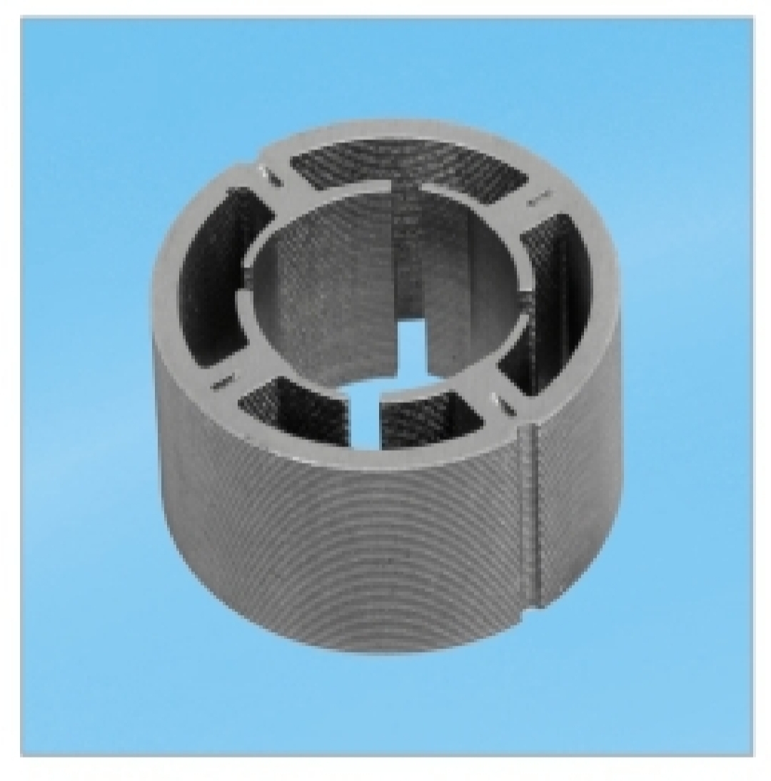
Stator: The stationary part with electromagnetic coils.
-
Rotor: The rotating part with permanent magnets.
-
Sensors: Hall-effect sensors to tell the controller the rotor's position.
-
Bearings: High-precision, often ceramic, bearings to handle high RPM.
-
Housing: A rigid structure to hold everything together and manage heat.
-
Controller: An Electronic Speed Controller (ESC) or a more advanced servo drive.
Step-by-Step Theoretical Construction:
1. Design and Specification
This is the most critical step. You must define:
-
Required Power (Watts) and Torque (Nm): Based on your CNC machine's size and what materials you plan to cut.
-
Operating Voltage and Current: Determines the thickness (gauge) of the wire for the coils.
-
Desired RPM (Revolutions Per Minute): Influences the number of magnetic poles.
-
Physical Size Constraints: Must fit in your machine's spindle mount.
2. Building the Stator
-
Core: The core is not solid steel; it's made from many thin layers of laminated electrical steel to reduce energy-wasting eddy currents. This lamination must be precisely stamped or laser-cut.
-
Windings: You must wind copper wire through the slots in the stator core. The number of turns, the pattern (e.g., delta vs. star configuration), and the wire gauge are complex calculations that determine the motor's KV rating (RPM per Volt). This requires a winding jig for consistency.
3. Building the Rotor
-
Core: Typically made from a solid or laminated steel cylinder that attaches to the motor's shaft.
-
Magnets: Very strong Neodymium (NdFeB) magnets are glued into place on the core with a specific alternating polarity (North, South, North, South...). The number of magnet poles must be designed in relation to the number of stator poles. The magnets must be perfectly balanced and securely attached; a loose magnet at high RPM is a catastrophic projectile.
4. Assembly and Integration
-
Shaft and Bearings: The shaft must be perfectly straight and machined to high tolerances. The bearings must be rated for the maximum speed and load.
-
Hall Sensors: These are soldered onto a small PCB and positioned precisely inside the motor housing so they can detect the passing magnet poles without interfering with the rotor.
-
Assembly: The stator is pressed into the housing. The rotor is carefully inserted into the stator with a tiny, consistent air gap (often less than 1mm). Any misalignment will cause the rotor to rub against the stator, destroying the motor.
5. The Controller (ESC)
The motor is useless without a smart controller.
-
Function: The controller takes a DC power input and a command signal (from the CNC controller) and delivers timed, three-phase AC power to the stator windings.
-
Challenge: You can buy generic ESCs for drones, but they are not suited for the high-torque, low-speed demands of CNC axis movement. For a spindle, you need a controller capable of smooth operation across a wide speed range. For servo applications, you need a true servo drive that works with the encoder for precise positional control.
6. Testing and Balancing
This requires specialized equipment. The assembled rotor must be dynamically balanced on a balancing machine. Weights are added or removed until vibration is negligible. Unbalanced operation will destroy the bearings and make the CNC machine unusable.
The Practical and Highly Recommended Alternative
Instead of building a motor, your project should be integrating and controlling a professional BLDC motor.
-
Buy a BLDC Spindle Motor: Companies like CNC4Newbie, Makita, Huanyang, and Eriksson make excellent air- or water-cooled spindles with matched controllers. This is by far the most common path for DIY CNC builders.
-
Buy a BLDC Servo Motor: For axis movement, companies like Teknic, ClearPath, or ODrive offer integrated servo kits that include the motor, encoder, and driver all in one package. They are connected to a CNC controller (like a Mesa card, Mach4, or LinuxCNC) and are tuned via software.
Conclusion:
While understanding the principles of a BLDC motor is valuable, the process of building one that is safe, precise, and powerful enough for CNC work is a task for specialized factories with millions of dollars in equipment.
Your time and money are far better spent selecting the right off-the-shelf professional motor and learning how to integrate it with your CNC controller and software. This is a challenging and rewarding project in itself.
What is rice cooker BLDC Motor?
Why BLDC Motor is important for CNC machine?
Related Article


