
How to Make Axial Flux Motor Lamination Core
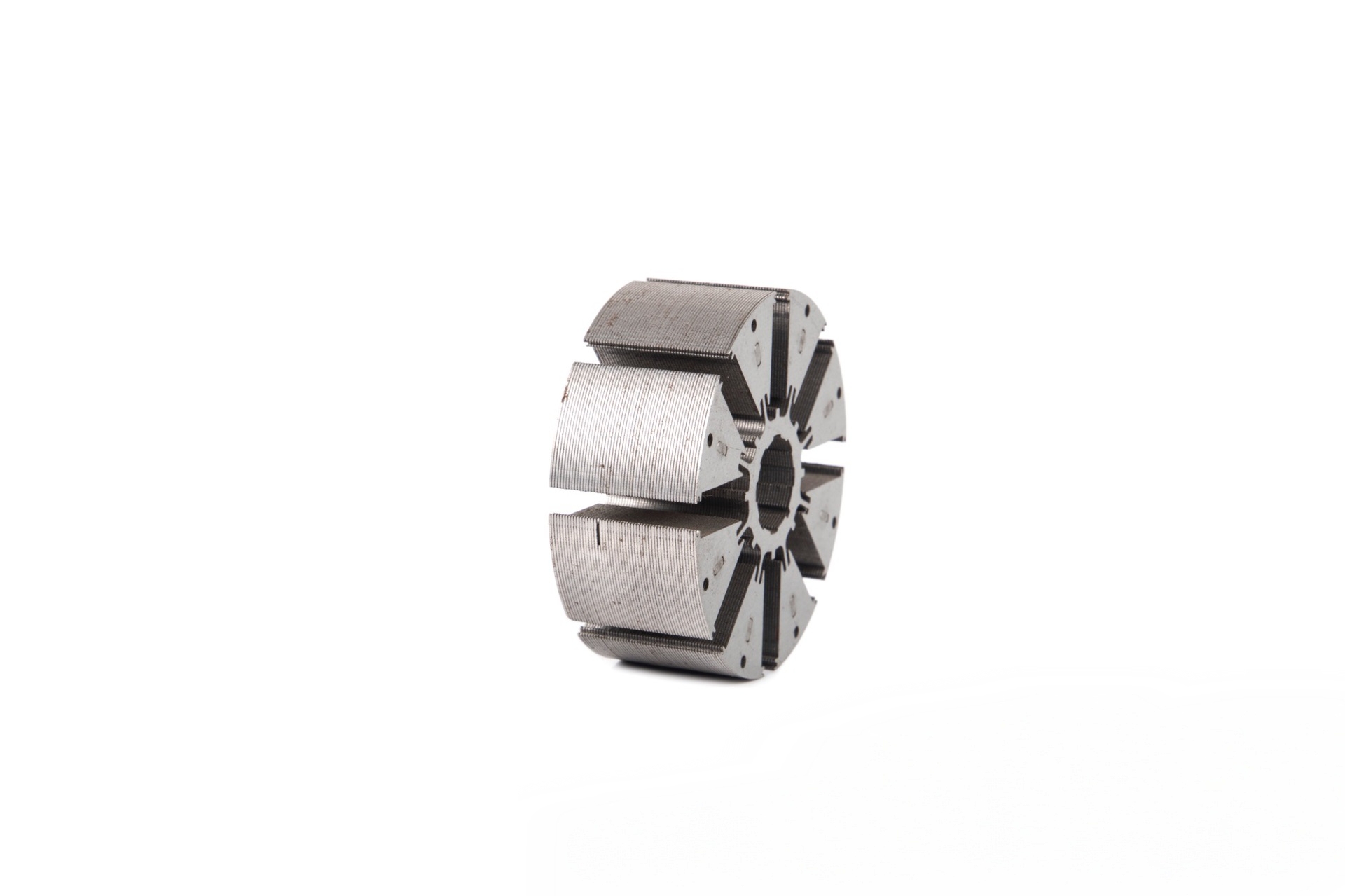
How to Make Axial Flux Motor Lamination Core: The Compact Powerhouse
Table of Contents
-
Introduction to Axial Flux Motor Cores
-
Key Materials and Design Fundamentals
-
Step-by-Step Manufacturing Process
-
Axial Flux vs. Inrunner Lamination Cores: A Comparison
-
Universal Disc Motor Core Parameters
-
Expert Insights on Performance and Trends
-
Frequently Asked Questions (FAQ)
Introduction to Axial Flux Motor Cores
The axial flux motor lamination core is the defining heart of a revolutionary motor topology known for its exceptional power and torque density. Unlike the cylindrical cores of common radial flux motors, axial flux cores are disc-shaped, with the magnetic flux flowing parallel to the motor's axis of rotation. This compact "pancake" geometry enables shorter, more efficient magnetic flux paths and allows for innovative multi-rotor, single-stator arrangements. The core's primary role is to provide a high-performance, low-loss path for the magnetic field while holding the copper windings. Manufacturing these unique cores requires specialized processes to achieve their signature thin, disc-like profile.
Key Materials and Design Fundamentals
The design and material choice are critical for overcoming the inherent challenges and unlocking the benefits of axial flux architecture.
-
Material: Ultra-thin non-oriented electrical steel (NOES) laminations, typically ranging from 0.1mm to 0.2mm in thickness, are almost mandatory. These thin laminations are crucial to minimize eddy current losses in the large, flat plane of the core where flux alternates at high frequency. High-grade silicon steel (e.g., M235-35A, M250-35A) is commonly used.
-
Core Design: There are two main stator core configurations:
-
Yokeless (or Torus) Design: The core consists only of individual, separate laminated teeth, arranged in a ring. There is no back-iron (yoke) connecting them, which significantly reduces weight and core loss.
-
Back-Iron Design: A more traditional disc with slots, featuring a full back-iron to complete the magnetic circuit, offering structural simplicity.
-
Step-by-Step Manufacturing Process
H4: 1. Material Selection and Blanking
The process starts with selecting high-quality, insulated electrical steel coils of the required thin gauge. For yokeless designs, steel sheets are stamped into precise individual tooth segments. For a full-disc core, the process is similar to creating a standard stator lamination but in a large-diameter, thin-disc form.
H4: 2. Building the Lamination Stack
This is a critical and distinct phase. For a yokeless core, the individual laminated teeth are assembled radially into a support structure or mold. For a full-disc core, laminations are stacked and aligned.
-
Stacking Method: Due to the large diameter and thin stack height, traditional interlocking is difficult. Common methods include:
-
Precision Gluing/Bonding: Using adhesive between each lamination.
-
Vacuum Pressure Impregnation (VPI): Stacking laminations and bonding them into a solid block with resin.
-
Spiral Winding (Slinky Type): For some designs, a pre-cut strip can be spirally wound to form the slotted disc, a technique related to the one detailed in our blog on How to make slinky hub motor lamination core?.
-
H4: 3. Consolidation and Curing
The assembled stack is placed under pressure in a fixture and cured in an oven (for adhesives) or processed through a VPI system. This consolidation phase is vital to create a rigid, monolithic core that can withstand significant electromagnetic and mechanical forces without vibration or delamination.
H4: 4. Machining and Finishing
The cured core block undergoes precision machining. Key operations include grinding the face to ensure perfect flatness and parallelism, which is critical for maintaining a consistent air gap in the axial direction. The outer and inner diameters may also be machined to final tolerances.
H4: 5. Insulation and Final Assembly
For yokeless segmented cores, an insulating bobbin or sleeve is often over-molded or fitted onto each tooth. For slotted disc cores, slot liners are inserted to provide electrical insulation between the core and the windings before the coil insertion or winding process begins.
Axial Flux vs. Inrunner Lamination Cores: A Comparison
| Feature | Axial Flux Motor Lamination Core | Traditional Inrunner Motor Lamination Core |
|---|---|---|
| Geometry & Flux Path | Disc-shaped (flat pancake). Flux flows parallel to the axis. | Cylindrical. Flux flows radially through the core. |
| Power/Torque Density | Extremely high. Short, direct flux path and compact package. | Moderate to good. Longer, radial flux path. |
| Active Material Use | Highly efficient, especially in yokeless designs with minimal inactive material. | Contains a significant amount of back-iron, which is magnetically active but adds weight. |
| Thermal Management | Excellent. Large, flat surfaces facilitate direct cooling via adjacent plates or liquid jackets. | Challenging; heat must travel radially outward from inside the winding slots. |
| Manufacturing Complexity | High. Precise flatness, thin laminations, and complex stacking/bonding required. | Lower, well-established. High-speed stamping and automated stacking are standard. |
| Rotor-Stator Arrangement | Enables compact dual-rotor, single-stator designs for double the active air-gap area. | Typically single rotor inside/outside a single stator. |
| Primary Applications | High-performance EVs, aerospace, traction, applications where compactness and low weight are critical. | Industrial drives, appliances, EVs (as traction or ancillary), robotics (high-speed). |
Expert Viewpoint: Prof. James Mueller, a pioneer in advanced motor topologies, comments: "The axial flux motor lamination core isn't just a different shape; it rethinks the electromagnetic circuit. Its unmatched surface-area-to-volume ratio is a double win: it allows for more efficient heat dissipation and, in multi-rotor setups, effectively doubles the torque-producing area. The manufacturing challenge shifts from high-speed stamping to precision assembly and bonding, a trade-off for achieving revolutionary power density."
Universal Disc Motor Core Parameters (Axial Flux Type)
The table below outlines common parameters for axial flux motor lamination cores, which are a subset of disc-type motors.
| Parameter | Typical Range / Specification |
|---|---|
| Outer Diameter (OD) | 100 mm to 500+ mm |
| Inner Diameter (ID) | 50 mm to 300+ mm (defines the "donut" shape) |
| Stack Length (Thickness) | 10 mm to 40 mm (notably short compared to OD) |
| Lamination Thickness | 0.1 mm, 0.2 mm (critical for performance) |
| Material Grade | M235-35A, M250-35A, or thinner NOES equivalents |
| Number of Slots/Teeth | 12 to 48 |
| Core Type | Yokeless Segmented Teeth or Full Slotted Disc |
| Stacking/Bonding Method | Gluing, VPI, or Spiral Winding |
| Key Tolerance | Face Flatness (often < 0.02mm) |
Frequently Asked Questions (FAQ)
Q1: Why is axial flux motor technology becoming so popular for electric vehicles?
A: Its primary advantage is exceptional power and torque density in a compact, lightweight package. For EVs, this means more power from a smaller motor, freeing up space for batteries and reducing overall vehicle weight, directly extending range. The excellent thermal performance also supports sustained high-power output.
Q2: What is the biggest manufacturing challenge for these cores?
A: Achieving and maintaining perfect flatness and parallelism across the large disc faces while using ultra-thin, fragile laminations. Any warping or unevenness leads to an inconsistent air gap, causing vibration, noise, and performance loss. The bonding and curing process is critical to control this.
Q3: Can these motors run at high speeds like inrunner motors?
A: Typically, they are optimized for high-torque, lower to medium RPM applications. The large diameter can create centrifugal force challenges at very high speeds. For extremely high-speed applications, a cylindrical inrunner motor lamination core (as described in our previous blog) is often more suitable due to its robust mechanical structure.
Q4: Is the "yokeless" design always better?
A: It offers superior weight savings and lower core loss, as it eliminates the magnetically inactive back-iron. However, it is structurally more complex, requiring a robust non-magnetic support structure to hold the individual teeth against electromagnetic forces. The choice depends on the priority of weight vs. structural simplicity.
Q5: How does the manufacturing process differ from a standard radial flux stator?
A: The fundamental difference is moving from high-volume stamping and automated stacking (for radial cores) to precision assembly of thin laminations with an emphasis on bonding and precision face grinding. The processes are more akin to creating a high-precision mechanical part than a traditional mass-produced lamination stack.
What is self-bonding motor lamination stacks?
How to Make Slinky Hub Motor Lamination Core?
Related Article


