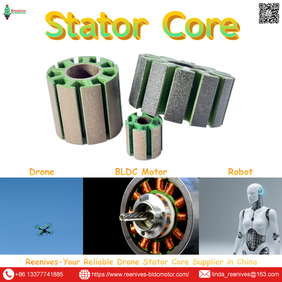
What is Relationship Between Stator and Motor in Drone?
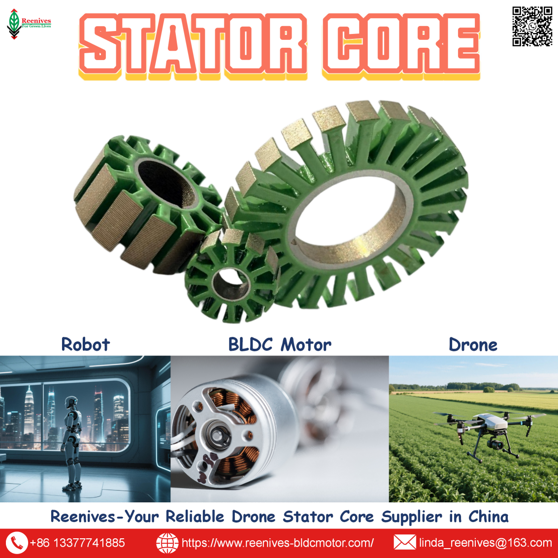
What is the Relationship Between Stator and Motor in Drone? The Stator Is the Torque Ceiling — Everything Else Just Spins Around It
If your drone motor hits 100% throttle and still cannot hold altitude, the problem is almost never the propeller or the ESC. It is the stationary component you never see spinning: the stator. Engineers and procurement teams routinely treat the stator as one line item inside a Drone Motor BOM, but the relationship between stator and motor is not a parts-list relationship — the stator sets the motor’s torque ceiling, its thermal limit, and its vibration signature before a single rotor magnet is installed.
This breakdown answers the long-tail question at the level that matters for specification and sourcing: how the stator functions as the motor’s electromagnetic reference, which slot-pole and lamination parameters actually move the thrust stand, and how a stator-side defect propagates into bearing failure and flight loss. Every figure below is tied to a published measurement standard or a defined test condition, so it can be checked against a supplier’s data rather than accepted on description alone.

In this guide — jump to the section your project needs:
- What Is the Relationship Between Stator and Motor in a Drone? The Electromagnetic Division of Labor
- Stator Configurations That Define Motor Behavior: 12N14P, 9N6P, 12N10P and Outrunner Architecture
- Stator Parameters That Set Motor Output: Kt, Air-Gap Flux Density, Iron Loss, and Eccentricity
- Application Profiles: Which Stator Parameter Binds Which UAV Mission
- A 5-Step Stator-to-Motor Matching Workflow for Propulsion Engineers
- FAQ: Slot-Pole, KV/Kt, Iron Loss, and Eccentricity
- Summary: The Stator Is the Motor’s First Specification
What Is the Relationship Between Stator and Motor in a Drone? The Electromagnetic Division of Labor
A drone brushless motor is a permanent-magnet synchronous machine. The rotor carries permanent magnets and produces the air-gap magnetic field. The stator carries the windings and, when energized, produces a rotating magnetic field that interacts with the rotor field to generate torque. The torque developed at the shaft varies directly with the product of armature current and air-gap magnetic flux density, related through the motor torque constant Kt. In that sense, the stator is not a component inside the motor — it is the structure that makes the motor a motor.
The stator’s job has two halves that are often conflated. The copper windings carry current and produce magnetomotive force; the laminated electrical steel core concentrates the flux and provides a low-reluctance path. Remove or degrade either half and the motor’s torque per amp falls — not because the rotor changed, but because the magnetic circuit the stator defines has changed. Electrical steel laminations are the foundation of the electromagnetic circuit, and their material grade, thickness, stamping quality, and coating directly determine core loss, heat generation, stacking factor and magnetic flux density, and mechanical strength and vibration resistance.
This division of labor explains a procurement reality that catches many buyers: two Drone Motor suppliers can quote the same KV, the same outer diameter, and the same 12N14P designation, and still deliver motors with different torque constants and different thermal margins. The slot-pole combination defines the basic structure, but it does not directly determine performance — different turns, wire sizes, magnets, air gaps, stator sizes, and stack heights change KV, torque, and efficiency.
The specification translation: “Stator and motor” is not a parts relationship; it is a causal relationship. The stator’s slot-pole geometry sets the winding factor and cogging profile; its lamination grade sets iron loss at the electrical frequency; its stacking factor and concentricity set how much of the designed flux density survives manufacturing. A motor datasheet that lists KV and thrust without naming these stator-level variables is describing an output, not the mechanism that produces it.
Stator Configurations That Define Motor Behavior: 12N14P, 9N6P, 12N10P and Outrunner Architecture
The most fundamental stator decision is the slot-pole combination. It determines the winding pattern, the winding factor, the cogging profile, and the upper speed limit — which is why the same stator diameter can be built into motors with very different flight characteristics.
| Slot-Pole Combination | Stator Slots | Rotor Poles | Winding Factor | Typical Application |
|---|---|---|---|---|
| 12N14P | 12 | 14 | 0.933 | Drones, multirotors; very low cogging |
| 9N6P | 9 | 6 | ~0.866 | Small motors, fans; low cogging |
| 12N16P | 12 | 16 | 0.866 | Hub motors, gimbals; very low cogging |
| 12N10P | 12 | 10 | — | Alternative drone combinations where higher speed or different torque profile is required |
| 24N22P | 24 | 22 | 0.949 | Gimbal motors; extremely low cogging |
Source: BLDC slot/pole combination reference table, winding factor values for concentrated windings; 12N14P drone motor structural analysis.
The reason 12N14P dominates drone propulsion is structural, not marketing. A three-phase 12-slot, 14-pole motor commonly uses a fractional-slot concentrated winding with q = 12 ÷ (14 × 3) ≈ 0.286; each coil wraps around a single stator tooth, which shortens the end windings and removes inactive copper that adds weight and resistance without contributing directly to electromagnetic conversion. The slight slot-pole asymmetry means the magnets never align with all teeth simultaneously, which dramatically reduces cogging torque — a critical property for smooth gimbal operation and responsive flight control.
Outrunner architecture amplifies the stator’s role. In an outer-rotor drone motor, the magnets operate at a larger effective torque radius than in an inner-rotor machine, which helps produce higher torque under similar conditions; the compact 12-slot concentrated-winding stator sits inside a rotor bell lined with 14 alternating poles. The stator is therefore not just the electromagnetic reference — it is the geometric center around which the torque radius is built.

Stator Parameters That Set Motor Output: Kt, Air-Gap Flux Density, Iron Loss, and Eccentricity
This is where the stator-motor relationship becomes measurable. Four stator-level parameters propagate directly into motor-level behavior, and each can be written into a supplier specification.
Torque constant Kt: the stator winding’s direct contribution
Kt relates output torque to input current. The stator winding — turns per coil, wire gauge, and wye versus delta connection — directly sets KV and therefore Kt: more turns means lower KV (more torque per amp) but higher resistance and heat; thicker wire reduces resistance but may not fit in the slots. The inverse relationship between KV and Kt is expressed through the back-EMF constant, Kt ≈ 60 / (2π × Kv). In published small brushless motor design data, an annular air-gap width between 0.2 mm and 0.35 mm with neodymium-bonded magnets produced an air-gap flux density of 4,500–5,000 gauss, a range in which motor constant Kt, torque ripple, cogging, and iron loss were well balanced.
Lamination grade and thickness: iron loss at the motor’s operating frequency
Core loss is a stator property that becomes motor heat. Common electrical steel grades in drone motors include 35WW250 and 50WW470, with thinner laminations (0.20 mm–0.35 mm) preferred for high-frequency operation. Reenives publishes typical iron loss of ≤ 12.5 W/kg at 1.0 T / 400 Hz for 0.20 mm material and ≤ 21 W/kg at 1.0 T / 400 Hz for 0.35 mm material, measured per IEC 60404-2; for >50,000 RPM operation, 0.20 mm high-silicon grade 20PN1200 is specified at iron loss ≤ 9.5 W/kg @ 1.0 T / 1000 Hz. The motor-level consequence is straightforward: at high electrical frequency, the stator’s iron loss becomes a larger share of total loss, and the grade selection determines how much of the input power never reaches the propeller.
Stacking factor and concentricity: how much of the design survives manufacturing
A stator core stamped from the correct steel can still underperform if the stack is loose or the bore is eccentric. Reenives publishes a typical stacking factor ≥ 97.0% (target 97.5%) measured by the weight/dimension method, and concentricity ≤ 0.02 mm for drone-grade laminated stator cores. Stacking factor minimizes non-magnetic gaps between laminations and directly affects achievable flux density; concentricity keeps the air gap uniform. These are separate line items from the mill certificate — and separate questions in a supplier audit.
Air-gap eccentricity: the stator defect that becomes a bearing failure
This is the parameter that connects stator quality to motor reliability. A non-uniform air gap produces uneven magnetic pull, which manifests as vibration and additional bearing load. Bearing damage then increases rotor eccentricity, which distorts the air-gap magnetic field and further amplifies electromagnetic vibration — a vibration-damage positive feedback loop. Static eccentricity can originate from stator core ovality or incorrect rotor-to-stator positioning at commissioning; dynamic eccentricity can be caused by a bent rotor shaft, bearing wear, or bearing misalignment. In BLDC motor failure statistics, bearing failure is the most common mechanical failure type, and high vibration and persistent overloading are among the most frequent failure contributors. The stator is where this chain starts.
Application Profiles: Which Stator Parameter Binds Which UAV Mission
The stator-motor relationship changes emphasis across mission classes. The table maps four UAV categories to the stator parameter that most directly constrains field performance.
| UAV Mission Class | Typical Prop / Battery | Binding Stator Parameter | What to Specify |
|---|---|---|---|
| 5-inch FPV / freestyle | 5×4.3 in / 6S; 1600–1900 KV | Iron loss at high electrical frequency; cogging for control response | 0.20 mm low-loss grade; 12N14P concentrated winding; concentricity ≤ 0.02 mm |
| 7–10 kg industrial quad | 15–18 in / 6S–12S; 320–170 KV | Kt at the hover point; stacking factor for flux density | Specify Kt or KV at the operating voltage; stacking factor ≥ 97% |
| 25 kg heavy-lift / logistics | 22–30 in / 12S–14S; 150–90 KV | Stator volume and thermal mass at continuous torque | Larger stator volume for the same KV; finished-stack iron loss report; matched stator-rotor pair |
| VTOL lift motor | 16–22 in / 6S–12S; 280–150 KV | Eccentricity and vibration over repeated transition cycles | Concentricity ≤ 0.02 mm; burr control; interlamination resistance on finished stack |
Application sizing reference: typical propeller, battery, and KV ranges by aircraft class.
For FPV platforms, the electrical frequency rises with RPM, which makes the 0.20 mm lamination grade the baseline rather than an upgrade. For heavy-lift logistics, torque capability scales roughly with stator volume, and heat dissipation scales with surface area — two motors of equal KV but different stator volume are different machines. For VTOL and inspection platforms, the eccentricity chain is the dominant reliability risk because repeated transition cycles load the bearings and any stator bore irregularity is amplified over hundreds of cycles.

A 5-Step Stator-to-Motor Matching Workflow for Propulsion Engineers
- Start from the propeller, not the motor. The propeller determines the torque and RPM the motor must deliver; the motor exists to serve it. Fix a candidate prop diameter from the frame and mass budget first. Sizing a motor in isolation produces the classic mismatch: a high-KV motor laboring a large prop and cooking itself amp by amp.
- Calculate per-motor hover thrust and max thrust. Per-motor hover thrust is MTOW divided by motor count. Max thrust is hover thrust multiplied by the thrust-to-weight target. For a 12 kg quad at 2:1, that is 3 kg hover and 6 kg max per motor.
- Use the thrust table to fix KV, then check the stator volume. Find rows delivering max thrust at 100% throttle with the candidate prop; hover thrust should fall at 45–55% throttle. KV is gearing, not a quality score: low KV means more torque per amp for large props; high KV means less torque per amp for small props spun fast. Then confirm stator volume: motor names encode stator diameter × height (2806 = 28 mm × 6 mm), and torque capability scales roughly with stator volume.
- Write the stator-level quantities into the specification. Name the slot-pole combination (12N14P for drone outrunners), the lamination grade and thickness (0.20 mm low-loss for high-frequency operation), the stacking factor (≥ 97%), and the concentricity (≤ 0.02 mm). These are the parameters that convert a motor’s rated KV and thrust into a repeatable finished product.
- Audit the failure chain, not just the datasheet. Ask for finished-stack iron loss at the operating frequency, burr height control, and interlamination resistance — because burrs that pierce the coating create local short circuits and hot spots even when the steel grade is correct. Then confirm the supplier controls stator bore roundness and rotor-to-stator alignment, because that is where the eccentricity-to-bearing-failure chain originates.
FAQ: Slot-Pole, KV/Kt, Iron Loss, and Eccentricity
What does 12N14P mean, and why is it the standard slot-pole combination for drone motors?
12N14P means 12 stator slots and 14 rotor poles (seven pole pairs). The combination is standard in FPV and small-drone outrunner motors because it delivers a fundamental winding factor of approximately 0.933 with a fractional-slot concentrated winding (q = 12 / (14 × 3) ≈ 0.286). The slot count is divisible by three for balanced three-phase operation, and because slots and poles are unequal, the magnets never align with all teeth simultaneously — which sharply reduces cogging torque. The winding factor describes how effectively the winding produces the useful fundamental magnetic field, but a high winding factor does not by itself guarantee high motor efficiency; copper loss, iron loss, magnet loss, and heat dissipation still determine actual performance.
Source: BLDC slot/pole combination reference and 12N14P winding analysis.
How does the stator core material and lamination thickness affect drone motor performance?
The stator core’s electrical steel grade and lamination thickness set core loss, which becomes heat at the electrical frequency the motor runs at. Thinner laminations (0.20 mm) are preferred for high-frequency operation in high-RPM drone motors, while 0.35 mm and 0.50 mm are used in general industrial BLDC and cost-sensitive designs. Common drone motor grades include 35WW250 and 50WW470. Reenives publishes typical iron loss of ≤ 12.5 W/kg at 1.0 T / 400 Hz for 0.20 mm material and ≤ 21 W/kg at 1.0 T / 400 Hz for 0.35 mm material, measured per IEC 60404-2. For >50,000 RPM operation, 0.20 mm high-silicon grade 20PN1200 is specified at iron loss ≤ 9.5 W/kg @ 1.0 T / 1000 Hz.
Source: Reenives electrical steel lamination specifications and high-RPM grade data.
How does air-gap eccentricity between stator and rotor cause drone motor failure?
Air-gap eccentricity — a non-uniform gap between stator bore and rotor outer diameter — produces uneven magnetic pull. This manifests as vibration and additional bearing load. Bearing damage then increases rotor eccentricity, which distorts the air-gap magnetic field and further amplifies electromagnetic vibration, forming a vibration-damage positive feedback loop. Static eccentricity can originate from stator core ovality or incorrect rotor-to-stator positioning at commissioning; dynamic eccentricity can be caused by a bent rotor shaft, bearing wear, or bearing misalignment. High vibration and persistent overloading are among the most frequent failure contributors in BLDC motors, and bearing failure is the most common mechanical failure type.
Source: BLDC motor failure analysis literature on eccentricity, bearing failure, and vibration feedback.
What stacking factor and concentricity should a drone stator core hold?
Reenives publishes a typical stacking factor of ≥ 97.0% (target 97.5%), measured by the weight/dimension method, and concentricity ≤ 0.02 mm for its laminated silicon steel stator cores. These are separate line items from the steel grade: a core stamped from the correct 0.20 mm material can still underperform if the stack is loose or the bore is eccentric. Stacking factor minimizes non-magnetic gaps between laminations and directly affects achievable flux density; concentricity keeps the air gap uniform and reduces the vibration that drives the eccentricity failure chain.
Source: Reenives laminated stator core specification table.
What is the relationship between KV, Kt, and stator design in a drone motor?
KV (RPM per volt, unloaded) and Kt (torque constant, torque per amp) are inversely related through the motor’s back-EMF constant: Kt ≈ 60 / (2π × Kv). The stator’s winding — turns per coil, wire gauge, and connection type — directly sets this relationship. More turns means lower KV (more torque per amp) but higher resistance and heat; thicker wire reduces resistance but may not fit the slots. The slot-pole combination determines the winding pattern, cogging torque, and vibration characteristics. In a typical drone motor, torque is produced by the interaction between the air-gap flux from the rotor permanent magnets and the stator currents, and the torque developed at the shaft varies directly with the product of armature current and air-gap magnetic flux density.
Source: BLDC winding and KV/Kt relationship reference.
Is the stator a single component, or an assembly, inside a drone motor?
At the motor assembly level, the stator is one of the functional assemblies alongside the rotor, bearings, windings, housing, and ESC. At the magnetic-circuit level, the stator is itself an assembly: dozens to hundreds of individually insulated electrical steel laminations, stacked and secured by interlocking, laser welding, or adhesive bonding, with slot and tooth geometry that accepts the copper windings. This distinction matters for procurement because the stator is a multi-variable manufactured stack — not a commodity stamping — and its finished performance depends on material grade, burr control, stacking method, and dimensional tolerance, not on the steel mill certificate alone.
Source: Electrical steel lamination construction and stator core manufacturing description.
Summary: The Stator Is the Motor’s First Specification
What is the relationship between stator and motor in a drone? The stator is the stationary magnetic circuit that converts current into torque, and in doing so it sets the three boundaries every other component operates within: torque per amp (through winding design and air-gap flux density), heat per watt of input (through lamination grade and iron loss), and vibration per revolution (through concentricity and air-gap uniformity). The rotor spins, the ESC commutates, and the propeller loads the shaft — but the stator defined the ceiling before any of them were chosen.
The practical consequence for procurement and R&D is that the stator belongs in the first column of the motor specification, not the bill of materials. A 12N14P concentrated winding delivers a 0.933 winding factor and low cogging, but only if the lamination stack holds its stacking factor and the bore holds its concentricity. A 0.20 mm low-loss grade cuts iron loss at high electrical frequency, but only if burrs do not pierce the interlamination coating. And an air gap held uniform below 0.02 mm keeps the eccentricity-to-bearing-failure chain from starting. These are the stator-level questions that separate a motor that meets its thrust table from one that meets it on paper only.
Matching a stator to a drone motor design?
Reenives manufactures laminated silicon steel stator and rotor cores in 0.20 mm / 0.35 mm non-grain-oriented grades, with stacking factor ≥ 97%, concentricity ≤ 0.02 mm, epoxy powder coating, and matched stator-rotor pairs for drone brushless motors. Send your slot count, stack height, and target KV or Kt for a sample evaluation and finished-stack iron loss data.
WhatsApp: +86-13377741885
Email: linda_reenives@163.com
Official website: www.reenives-bldcmotor.com
Dongguan Runlu Motor Technology Co., Ltd.
Reenives — Drone Motor One-Stop Solution Supplier
Reenives is a professional drone stator core manufacturer, founded in 2022. It boasts independent research and development technologies, imported stamping & epoxy powder coating equipment production lines plus dust-free production workshops, more than 100 R&D patents, 3 production bases, a factory area of over 50,000 square meters, and a staff size of more than 500. From production to sales, we support bulk purchasing, private mould development, and sample making, and can provide tailor-made perfect solutions for your production and usage scenarios. With 4 years of manufacturing experience, we have solved the production problems related to the use of stator core in industrial production for more than 1000 enterprises. We can ship globally (with complete export qualifications). Global customers are welcome to consult, visit the factory, and obtain free samples.
12N14P concentrated winding cores0.20 mm / 0.35 mm NO silicon steelStacking factor ≥ 97%Concentricity ≤ 0.02 mmMatched stator + rotor pairsGlobal export qualifications
What is PCB Stator Motor?
Related Article