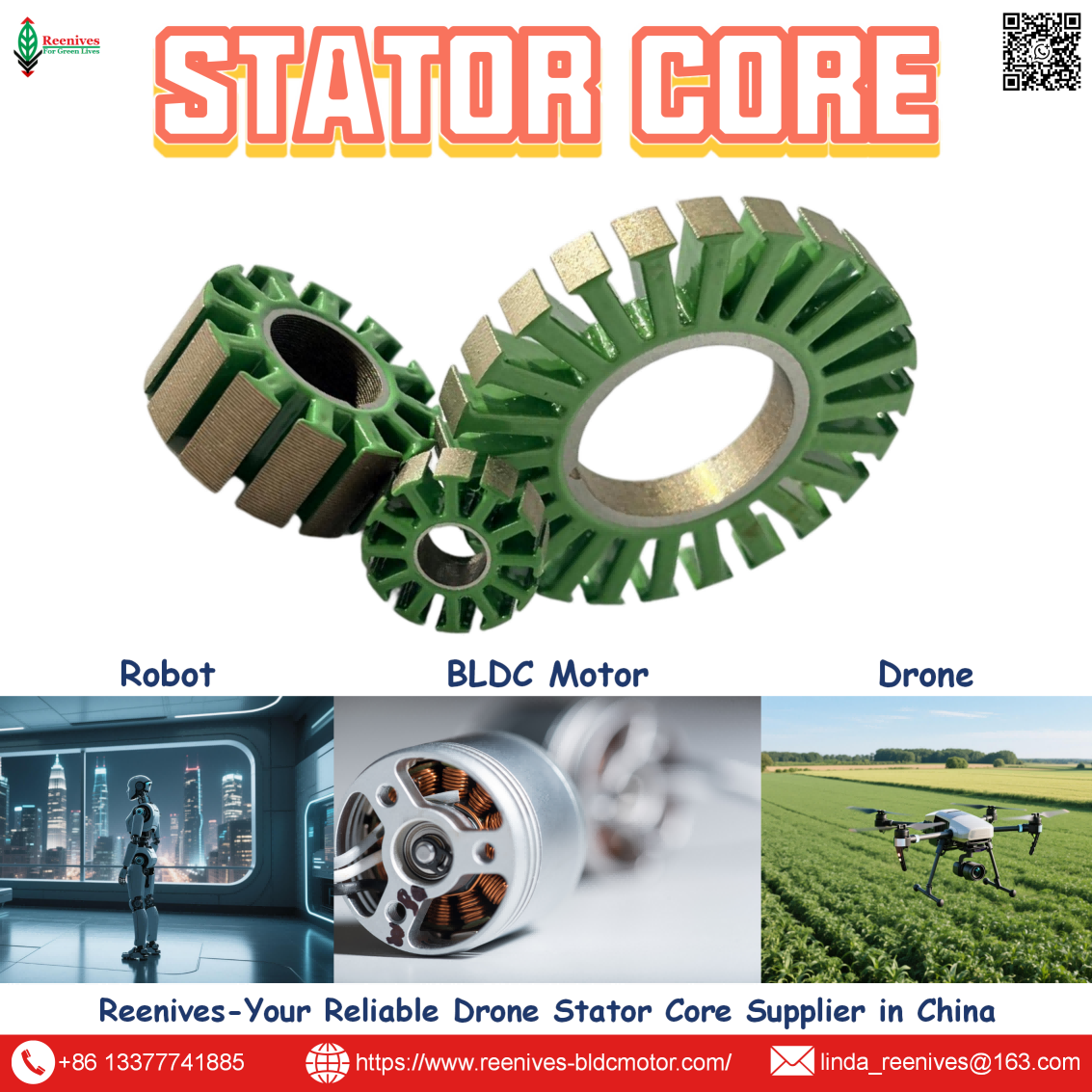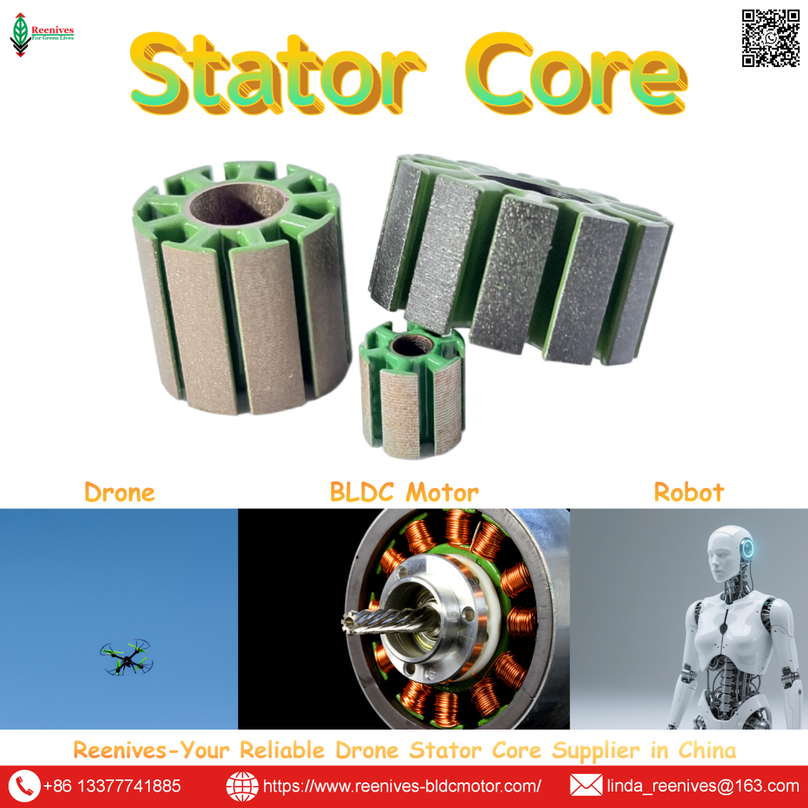
How Many Components Included in a Drone Motor?

How Many Components Included in a Drone Motor? The Count Is Six — the Stator Core Is the One That Decides Thrust and Heat
If your drone motor sags at minute ten or your robot joint trips on overcurrent, the component count did not cause it. A brushless Drone Motor can be broken down into a tidy list of functional assemblies, and that list will not tell you why one propulsion unit holds thrust through a full agricultural spray cycle while another loses it under thermal load. The variable that separates the two sits inside the stator assembly: lamination thickness, electrical steel grade, stacking factor, and concentricity. Those four parameters determine the core loss that becomes heat, the air-gap uniformity that becomes vibration, and the flux density that becomes torque.
This guide answers the component-count question directly — then moves to the parameters a procurement engineer or motor R&D team should actually qualify. Every performance number below is tied to a controlled test or a defined measurement standard, so it can be written into an RFQ or checked against a supplier’s finished-stack report.

In this guide — jump to the section your project needs:
- What Counts as a “Component” in a Drone Motor? Six Assemblies, and the Stack Inside One of Them
- Stator Core Architectures for Drone Motors: One-Piece, Segmented, Split-Tooth
- Stator Core Parameters That Move the Thrust Stand: Test Data and Measurement Standards
- Application Profiles: Which UAV Mission Demands Which Core Priority
- A 5-Step Stator Core Qualification Workflow for Motor Engineers
- FAQ: Stator Core Parameters Engineers Actually Ask About
- Summary: Specify the Core, Not Just the Count
What Counts as a “Component” in a Drone Motor? Six Assemblies, and the Stack Inside One of Them
A UAV-grade brushless DC motor is conventionally described as six key functional assemblies: the stator, the rotor with permanent magnets, the bearings, the windings, the housing and cooling structure, and the electronic speed controller (ESC) that commutates the phases. A teardown inventory can push the “part count” higher by adding the shaft, retaining rings, hall sensor PCB, and phase connectors. But that count is an inventory answer, not an engineering answer.
The distinction that matters for a Drone Motor is this: the stator is not one component — it is an assembly of dozens to hundreds of individually insulated electrical steel laminations, stacked and secured into a single magnetic circuit. At the stack level, the variables that separate a high-performance core from a commodity stamping are:
- Lamination thickness — commonly 0.20 mm or 0.10 mm for high-RPM drone motors, 0.35–0.50 mm for cost-sensitive designs.[reference:0]
- Interlamination insulation — C5 or C6-class coatings that block eddy currents between layers.[reference:1]
- Stacking method — interlocking tabs, laser welding, or adhesive bonding, each with a different stacking factor and vibration signature.[reference:2]
- Slot and tooth geometry — the profile that accepts copper windings and shapes the flux path; most drone motors follow a 12N14P configuration, 12 stator poles and 14 rotor magnets.[reference:3]
Procurement translation: When a supplier quotes a “stator core,” they are quoting a manufactured magnetic stack, not a stamped sheet. Two cores with identical outer diameter, bore, and slot count can differ measurably in finished performance depending on burr height, punching stress, and stacking method. That is why the component-count question should always be followed by a finished-stack specification audit — not a mill certificate review alone.
Stator Core Architectures for Drone Motors: One-Piece, Segmented, Split-Tooth
The component count does not change with architecture, but the core design does. Three configurations cover most UAV brushless motor designs, and each imposes a different qualification focus.
| Architecture | Core Feature | Typical Fit | Qualification Focus |
|---|---|---|---|
| One-piece laminated ring | Full-ring stamping, interlocked or welded | Medium-to-high-volume UAV motors; heavy-lift and agricultural platforms | Concentricity and stacking factor at production volume |
| Segmented stator core | Individual teeth stamped and wound separately, then assembled | High-slot-fill drone motors where copper volume is the design driver | Assembly concentricity; segment-to-segment air-gap consistency |
| Split-tooth / custom profile | Separate teeth or private-mould tooth geometry for specific KV and torque targets | Application-specific propulsion and heavy-payload logistics | Private mould development lead time; finished-stack core loss verification |
For drone BLDC motors, a segmented core with tight concentricity below 0.03 mm is used to keep the air gap uniform — a direct lever on torque smoothness and noise reduction.[reference:4] Bonded stacks further suppress harmonic vibration in FOC-driven applications, while interlocked stacks suit volume production where mechanical assembly speed matters.[reference:5] The architecture choice is therefore not cosmetic; it changes what the supplier must measure and what the buyer must audit.
Stator Core Parameters That Move the Thrust Stand: Test Data and Measurement Standards
This is where the component-count conversation becomes an engineering conversation. The four parameters below are the ones that appear in controlled comparisons and supplier qualification reports.
Lamination thickness: the eddy-current lever
Very thin laminations, generally 0.2 mm thick, are preferred for drone motors to reduce core loss; the high pole count raises electrical frequency even at ordinary flight RPM, which increases eddy-current loss in the stator core.[reference:6] In a controlled swap on a standard drone BLDC motor — all other design parameters held constant — moving from 0.35 mm standard silicon steel to 0.20 mm low-loss high-grade steel produced measurable deltas:
| Measured Parameter | 0.35 mm Standard Silicon Steel | 0.20 mm Low-Loss Steel | What It Means for a Drone Motor |
|---|---|---|---|
| Motor efficiency | Baseline | +1–2% | Longer flight time at the same battery capacity |
| Core + winding temperature | Baseline | −10°C or more | Slower insulation aging; greater thermal margin in enclosed chassis |
| Dominant loss mechanism | Eddy current in thicker laminations | Shortened eddy-current path | Lower heat generation at high electrical frequency |
Data source: Reenives controlled lab test on a standard drone BLDC motor, 2026; all other design parameters held constant.[reference:7] Supplementary industry analysis notes that ultra-thin silicon steel (0.05–0.15 mm) with a uniform adhesive insulation layer can reduce eddy-current losses by 20–30% under high-frequency operation.[reference:8]
Core loss: specify it on the finished stack, at a defined reference point
The measurement standard behind a core-loss number matters as much as the number itself. IEC 60404-2 defines the Epstein-frame method for specific total loss of electrical steel at 50 Hz / 1.5 T, with the stipulation that no external stress be exerted on the specimen.[reference:9] That condition is exactly why a finished-stack report is more informative than a raw material certificate: stamping and stacking introduce stress and burrs that the Epstein specimen does not experience. Require the supplier to state core loss at a defined polarization and frequency — for example P15/50 — on the stacked core, not only on the steel datasheet.
Stacking factor: a separate line item, not an assumption
A stator core built from the correct 0.20 mm steel can still underperform if the stack is loose. Reenives publishes a typical stacking factor of ≥95% for its stator and rotor laminations; the parameter is listed separately because it minimizes the non-magnetic gaps between layers and directly affects achievable flux density.[reference:10] The practical implication for a buyer: moving from a 96% to a 98% stacking factor increases effective magnetic flux density by roughly 6% without any change to the steel grade on the mill certificate. Stacking factor is therefore a qualification question in its own right.
Concentricity and burr control: the variables that hide behind “same material”
For drone BLDC motors, target concentricity below 0.03 mm between stator bore and rotor outer diameter to keep the air gap uniform; a non-uniform gap causes uneven magnetic pull, vibration, cogging torque, and accelerated bearing wear.[reference:11] Reenives publishes a typical critical-dimension tolerance of ±0.05 mm for its stator and rotor laminations, with tighter values available for high-precision drone cores.[reference:12] Burr height is the other half of the pair: burrs can pierce the interlamination coating during stacking, creating local short circuits that generate eddy currents and hot spots even when the steel specification is excellent. The qualification question is not “what steel grade?” but “what burr control and what interlamination resistance on the finished stack?”

Application Profiles: Which UAV Mission Demands Which Core Priority
Component count is identical across missions; the stator core priority is not. The table maps four industrial UAV categories to the core specification that most directly affects field reliability.
| Application | Typical Motor Configuration | Stator Core Priority | Specification to Write |
|---|---|---|---|
| Agricultural spraying UAV | Low-KV outrunner; continuous duty near thermal limit | Thermal stability and insulation aging resistance | 0.20 mm low-loss steel; C5 coating; finished-stack P15/50 report |
| Industrial inspection / surveying drone | Medium-KV outrunner; precision hover | Torque smoothness and low vibration | Concentricity <0.03 mm; uniform air gap; interlocked or bonded stack |
| Heavy-lift / logistics UAV | Low-KV outrunner; high torque at large propeller diameter | Flux density capacity without saturation | Stacking factor ≥95%; adequate stack height; matched stator-rotor pair |
| FPV / high-RPM drone | High-KV outrunner; rapid throttle changes | Eddy-current loss at high electrical frequency | 0.20 mm or 0.10 mm laminations; segmented or one-piece thin-gauge core |
For agricultural drones operating near the thermal limit, the 10°C+ temperature reduction from a 0.20 mm core is a reliability variable, not a comfort variable — slower insulation aging extends service life in an environment where a motor failure ends a spray mission.[reference:13] For FPV platforms, the electrical frequency rises with throttle changes and RPM, which is why thin-gauge laminations are the baseline rather than an upgrade.[reference:14] For heavy-lift platforms, stacking factor and matched stator-rotor geometry matter more than raw lamination thickness, because a loose or mismatched stack wastes the flux density the design paid for.

A 5-Step Stator Core Qualification Workflow for Motor Engineers
- Fix the mission envelope before the motor. Takeoff weight, payload, required flight time, and ambient temperature set the thermal and torque ceiling. A continuous-duty agricultural platform and a short-burst FPV quad do not share core priorities.
- Choose the propeller diameter, then the KV. Larger propellers demand lower-KV, higher-torque motors. The stator core must provide sufficient slot area for copper fill and enough stack height to avoid magnetic saturation at the required torque.
- Match the voltage platform and verify the thrust table at the working point. Request the thrust table and confirm the motor’s high-efficiency region overlaps the intended hover and climb throttle. A motor operating at its peak-power limit is outside its thermal design margin.
- Audit lamination thickness and steel grade against the mission, not the catalog. For high-RPM or high-electrical-frequency operation, 0.20 mm low-loss steel is the reference; for cost-sensitive low-duty designs, 0.35–0.50 mm may be acceptable. Ask for the grade designation, not just “silicon steel.”
- Require finished-stack evidence, not material-only certificates. Ask for: core loss at a defined polarization and frequency on the stacked core; stacking factor; concentricity between stator bore and rotor OD; insulation coating class (C3/C4/C5/C6); burr height control; and interlamination resistance. Processing stress and burr-induced short circuits can degrade finished magnetic performance relative to the raw steel datasheet — which is why the stack-level report is the auditable artifact.
FAQ: Stator Core Parameters Engineers Actually Ask About
Does 0.20 mm lamination really make a measurable difference compared with 0.35 mm in a drone motor?
Yes. In a controlled swap on a standard drone BLDC motor — all other design parameters held constant — moving from 0.35 mm standard silicon steel to 0.20 mm low-loss high-grade steel improved efficiency by 1–2% and reduced core and winding temperatures by more than 10°C. The mechanism is shorter eddy-current paths per lamination. The benefit scales with electrical frequency, which is why high-pole-count drone motors see it at ordinary flight RPM.
Source: Reenives controlled lab test, 2026; all other design parameters held constant.[reference:15]
What core loss value should I write into a drone motor stator core specification?
For drone BLDC motor applications, specify core loss on the finished lamination stack at a defined reference point, not merely the raw steel mill certificate. IEC 60404-2 defines the Epstein-frame measurement of specific total loss at 50 Hz / 1.5 T. Require the supplier to report P15/50 on the stacked core, because punching stress, burr height and stacking method can degrade finished magnetic performance relative to the material datasheet.
Source: IEC 60404-2, methods of measurement of magnetic properties of electrical steel by means of the Epstein frame.[reference:16]
Why does a drone motor overheat even when low-loss electrical steel was specified?
The steel grade is one variable; the stack is another. Burrs on lamination edges can pierce the interlamination insulating coating during stacking, creating local interlaminar short circuits. Those short circuits generate eddy currents and hot spots even when the raw steel specification is excellent. The qualification question should be: what is the burr height control and what interlamination resistance was measured on the finished stack?
Source: Reenives engineering analysis of stator-core-related UAV motor failures.[reference:17]
What concentricity tolerance is acceptable between stator bore and rotor outer diameter?
For drone BLDC motors, a stator core with concentricity below 0.03 mm keeps the air gap uniform, which supports torque smoothness and reduces cogging and noise. A non-uniform air gap causes uneven magnetic pull, visible as vibration and accelerated bearing wear. Reenives publishes a typical critical-dimension tolerance of ±0.05 mm for standard stator and rotor laminations, with tighter values available for high-precision drone cores.
Source: Reenives stator/rotor lamination specifications and engineering guidance on segmented drone stator cores.[reference:18][reference:19]
Can stator and rotor cores be supplied as a matched pair for a drone motor?
Yes. Because the stator and rotor form a single magnetic circuit, matched pairs stamped from the same material on the same high-speed lines eliminate dimensional stack-up errors that occur when the two cores come from different production runs. Reenives engineers matched stator and rotor pairs specifically for drone brushless motors, with consistent air gaps and low core loss across the assembly.
Source: Reenives matched stator and rotor core documentation for drone brushless motors.[reference:20][reference:21]
What stacking factor should a drone stator core hold, and why does it matter if the steel grade is already correct?
A loose stack wastes the steel grade. Interlocked or bonded stacks from a precision supplier hold high stacking factors that minimize the non-magnetic gaps between laminations. Reenives publishes a typical stacking factor of at least 95% for its stator and rotor laminations; moving from 96% to 98% stacking factor increases effective magnetic flux density by roughly 6% without changing the mill certificate. Stacking factor is therefore a separate line item to audit, not an assumption.
Source: Reenives stator rotor lamination specification table.[reference:22]
Summary: Specify the Core, Not Just the Count
How many components are included in a Drone Motor? Six functional assemblies is the defensible inventory answer — stator, rotor with magnets, bearings, windings, housing, and ESC. But the specification that determines whether those six assemblies produce a propulsion unit that holds thrust through continuous load, or one that battles thermal degradation, is buried inside the stator: lamination thickness, steel grade, stacking factor, and concentricity.
The numbers are not abstract. A 0.35 mm to 0.20 mm lamination swap produced +1–2% efficiency and a 10°C+ temperature reduction in a controlled test with every other variable held constant.[reference:23] Concentricity below 0.03 mm supports uniform air gap and smoother torque.[reference:24] A stacking factor at or above 95% preserves the flux density the steel grade was selected for.[reference:25] Core loss measured on the finished stack, not just the mill certificate, is the auditable evidence that the finished magnetic circuit meets the design intent. These are the levers a procurement engineer can write into a purchase specification and a motor R&D team can verify on the thrust stand.
Ready to qualify a stator core against finished-stack data?
Reenives supplies matched stator and rotor cores, private mould development, and finished-stack documentation for drone brushless motors and other BLDC applications. Free samples are available for qualified engineering evaluations.
WhatsApp: +86-13377741885
Email: linda_reenives@163.com
Official website: www.reenives-bldcmotor.com
Dongguan Runlu Motor Technology Co., Ltd.
Reenives — Drone Motor One-Stop Solution Supplier
Reenives is a professional drone stator core manufacturer, founded in 2022. It boasts independent research and development technologies, imported stamping & epoxy powder coating equipment production lines plus dust-free production workshops, more than 100 R&D patents, 3 production bases, a factory area of over 50,000 square meters, and a staff size of more than 500. From production to sales, we support bulk purchasing, private mould development, and sample making, and can provide tailor-made perfect solutions for your production and usage scenarios. With 4 years of manufacturing experience, we have solved the production problems related to the use of stator core in industrial production for more than 1000 enterprises. We can ship globally (with complete export qualifications). Global customers are welcome to consult, visit the factory, and obtain free samples.
Finished-stack core loss reportsMatched stator + rotor pairs0.20 mm low-loss capabilityGlobal export qualifications
What is PCB Stator Motor?
What is Generator Stator Winding?
Related Article